The advantage of a resistor ladder DAC is that it's not a noise generator like a PWM DAC.
The disadvantage is that it's more expensive.
The temperature drift depends on the resistors used, for a 10ppm resistor from 10 to 45° C the thermal drift is practically null.
I don't know what kind of resistors have been used in the DAM1021, anyway a copper sheet placed on the ladder and on the switches can null the temp drift.
The 14 bit accuracy of the DAM1021 is determinated from the resistors tolerance, the math is not an opinion.
BTW, the TDA1540 is still a good DAC.
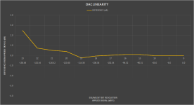
Because ASR says about the DAC1421 re: level linearity:
"The Soekris dac1421 produces near ideal response with variation of just 0.5 dB at -120 dBFS (20 bits). The limit of measurement is about 0.2 dB so this is almost as good as it gets."
Review and Measurements of Soekris dac1421 Multibit DAC | Audio Science Review (ASR) Forum
//
"The Soekris dac1421 produces near ideal response with variation of just 0.5 dB at -120 dBFS (20 bits). The limit of measurement is about 0.2 dB so this is almost as good as it gets."
Review and Measurements of Soekris dac1421 Multibit DAC | Audio Science Review (ASR) Forum
//
Already explained with math example, the accuracy is the precision of the ladder
Reference DAC Module - Discrete R-2R Sign Magnitude 24 bit 384 Khz
Reference DAC Module - Discrete R-2R Sign Magnitude 24 bit 384 Khz
Because ASR says about the DAC1421 re: level linearity:
Ah, Amir and his measurements... 🙂
1021
1541
Attachments

I don't know, the math is not an opinion.
The random combination of the resistors in the ladder will give different result from a device to another.
The calibration will give the same result for each device, real 24 bit ladder accuracy.
The calibration process will tell the precision of each exemplary.
The random combination of the resistors in the ladder will give different result from a device to another.
The calibration will give the same result for each device, real 24 bit ladder accuracy.
The calibration process will tell the precision of each exemplary.
Last edited:
Please explain more. The graphs you posted, where are they from? Please supply a reference maybe?
//
//
Well not math per see. But its all about the understanding of reality and how you defined the problem and setup the math. There one can go wrong.
//
//
Yes the Tda1540 despite its 13+1, 14 bits is sounding nice, I have still a Marantz cd players with it a,d philips cdm0 lens platine in it, all tweaked to death that may Lampizator face to become red...
So a fixed correction if I understand, not a sort of sensing with dynamic correction as I faultly believed ?
I believe the first Dam used smd Vishays resistors but I'm not sure about that information.
So a fixed correction if I understand, not a sort of sensing with dynamic correction as I faultly believed ?
I believe the first Dam used smd Vishays resistors but I'm not sure about that information.
Last edited:
eldam, we are talking measurements and specifications here - not subjective listening impression and tweak-mania.
//
//
Last edited:
Well not math per see. But its all about the understanding of reality and how you defined the problem and setup the math. There one can go wrong.
//
No way the math is wrong, but you can get different results from a device to another because the error combination in the ladder is random.
When I will calibrate my DAM1021 I will publish the real accuracy.
I will measure each bit voltage with a 8 1/2 digit DMM to calculate the suitable digital correction.
The calibration process will be automated by a Windows application.
The application send a signal to the DAC (to the FIFO Lite) in order to measure each bit voltage and then it stores the measurement from the DMM.
Finally the correction digit for each bit will be calculated.
Yes the Tda1540 despite its 13+1, 14 bits is sounding nice, I have still a Marantz cd players with it a,d philips cdm0 lens platine in it, all tweaked to death that may Lampizator face to become red...
So a fixed correction if I understand, not a sort of sensing with dynamic correction as I faultly believed ?
I believe the first Dam used smd Vishays resistors but I'm not sure about that information.
Yes , one time calibration.
Dynamic correction causes noise.
Dont forget to do all planned measurements also in the 1021 as stock, in order to be able to compare.
//
//
No way the math is wrong, but you can get different results from a device to another because the error combination in the ladder is random.
When I will calibrate my DAM1021 I will publish the real accuracy.
I will measure each bit voltage with a 8 1/2 digit DMM to calculate the suitable digital correction.
The calibration process will be automated by a Windows application.
The application send a signal to the DAC (to the FIFO Lite) in order to measure each bit voltage and then it stores the measurement from the DMM.
Finally the correction digit for each bit will be calculated.
That's a good tweak to correct this bad sounding dac 😎 !
Dont forget to do all planned measurements also in the 1021 as stock, in order to be able to compare.
//
I will measure the phase noise of the DAM1021 before and after the tweaking.
The accuracy of the ladder is not affected by the upgrade.
The FIFO Lite will apply software calibration not hardware correction.
- Home
- Source & Line
- Digital Line Level
- Implementing a true FIFO buffer with low phase noise clock on the Soekris DAM1021 DAC