I see how the OP's wording might be miscontrued.I see no series inductors anywhere in the above Tannoy crossover.
I see two in series. Not with each other but they are in series in the circuit. I believe that's what was intended.
Perhaps, but since we don't know the gauge of the coils, I was just wondering. I prefer air core in series and iron for shunting, unless we are talking very large chokes.To keep the dcr low on the series inductors, surely.
Well, the real experts will have to answer that, but since the series notch is for impedance flattening, wouldn't you just adjust the value of the resistor accordingly?Isn't the resistance of the air core inductor in the HF section necessary to the function of the series notch filter?
Edit: I seemed to have skipped over Allen's answer when typing this. Thank you Allen.
I see two in series. Not with each other but they are in series in the circuit. I believe that's what was intended.
However, Tubenstein said "two 1mH inductors ... wired in series ... for high pass filtering".
The two inductors to which you refer are 1 mH and 2 mH and are for low pass filtering.
I remain confused! 🤓
Isn't this just a 2.5 way crossover? Each woofer should have different value inductor. It may take care of baffle step diffraction.
Fair enough but I always think about a 2.5 way as having two identical drivers delivering different parts of the spectrum. I look at this as a 3 way.Isn't this just a 2.5 way crossover?
Go on, tell me I'm wrong...🙂
Well a somewhat consistent definition of N-way is having 2N-2 pass-filters. So a common 2.5-way has one fewer filter (a high pass) than a common 3-way. A 2-way could be tweeter+midwoofer or midtweeter+woofer. And 1.5-way could be fullrange+supertweeter or fullrange+subwoofer 🙂
(As for the subject not of this thread but the adjacent "hot" one, a proper 4-way then ought to have 6 pass-filters but I suspect many 4-different-driver speakers skip one or few 0.5's.)
(As for the subject not of this thread but the adjacent "hot" one, a proper 4-way then ought to have 6 pass-filters but I suspect many 4-different-driver speakers skip one or few 0.5's.)
Last edited:
Interesting. I see three different drivers, each offering a different response due to the filter network, regardless of any overlap. I call that a 3 way.
But is lowering resistance a goal in itself, I hear this argument a lot and I suspect I know where the concept originated? In any case, sure it's reasonable to consider efficiency at design time, and you don't want inductors getting too hot.To keep the dcr low on the series inductors, surely. Pretty standard. If the OP wants to upgrade the parts, though, heavier gauge air core would be the obvious way to go.
However isn't reducing the series resistance of an established design going to be a downgrade, unless you intend to compensate what you do?
Were not sure if it is a upgrade.
The inductors used were matched to the DCR of the factory coils.
So would be considered a direct replacement.
In all simplicity the core increases the magnetic field.
So in the audio world to get a large value inductor you need more wire
like any other inductor.
So yes pretty standard stuff
You get lower DCR because it requires less wire to get the same inductance value.
Wire gauge determines power handling.
So if you used heavier gauge wire.
Using a core you also greatly reduce its size.
Twist it up how ever you want.
Core inductor is a cost effective way to produce large ,low DCR coils.
Rather smart actually.
Conventional " 3 way" considered to have a bandpass
for the mid.
This case both woofers cover bass frequencies.
Then high frequency for tweeter
High pass / low pass only
no bandpass.
2 way.
Second woofer covers baffle step compensation.
considered .5 alignment.
So 2.5 way
@AllenB Yes, I agree. But I wasn't advocating reducing the resistance of this design or any other. Cal asked why iron cores were chosen for the low pass inductors, and I was just chipping in with the point (something I'm sure he was aware of) that this is often done to keep dcr low.
The OP has got us all scratching our heads. I'm just trying to help, like you and others.
My best guess is that Tubenstein has a pair of Tannoy DC2000s, and is trying to upgrade them by building new crossovers, to the same design as the originals, but with new parts. (This is quite commonly done with vintage Tannoys. Whether it's worthwhile, I rather doubt, personally.)
I think he has had someone measure the old crossover and prepare a circuit diagram. I also think his question in post 1 is based on a complete misreading of that circuit diagram.
Also, I don't think the dcr of the original inductors is shown, in the diagram: 6 ohms is way too much. It's probably the dcr of the drivers.
As for whether the DC2000 is a 2.5 way design, it's arguable. The LF portion of the dual concentric and the separate woofer are the same size (8 inch), and very similar, but obviously not identical. Neither is lowpassed, and the separate woofer rolls off first. I'd be happy to call that 2.5 way.
Last edited:
Sorry, that bit at the end should say: "...Neither is highpassed, and ... "
(too late to edit, dammit!)
(too late to edit, dammit!)
Z being impedance of drivers , yes
6 ohms be rather horrible inductor.
6 ohms being nominal, or crossover point or impedance with crossover.
Dont care.
There either 6 or 8 ohm speakers.
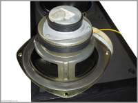
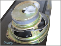
looks like same old stamp driver.
One has a tweet a doo , the other just has cap over the coil.
can see the unused mounting holes and hole in magnet for coaxial.
crossover mounted to jack plate.
pretty smart and straight forward stuff.


I have a question for you guys.
After stripping down the speaker, here are the DCR of stock inductors.
Tweeter 1mH DCR 4.5R
Midrange 1mH DCR 0.6R
Bass 2mH DCR 0.45R
Can I put 1mH copper foil DCR 0.8 ohm? Would it ruins the filter?
I already had the Jantzen 1mH air core made and DCR is 2.24R, and 1mH (DCR: 0.53R) and 2mH (DCR: 0.45R) for midrange and bass respectively, are iron core made by Jantzen. The one on the bass is iron core with disc.
I already had the Jantzen 1mH air core made and DCR is 2.24R, and 1mH (DCR: 0.53R) and 2mH (DCR: 0.45R) for midrange and bass respectively, are iron core...
I've added the crossover schematic here for easy reference:
Is "Tweeter 1mH DCR 4.5R" replaceable with "Jantzen 1mH air core DCR 2.24R"?
What say you @AllenB?
You haven't said where you want to use the copper foil inductor. In the tweeter circuit? Or on the mid/bass?I have a question for you guys.
After stripping down the speaker, here are the DCR of stock inductors.
Tweeter 1mH DCR 4.5R
Midrange 1mH DCR 0.6R
Bass 2mH DCR 0.45R
Can I put 1mH copper foil DCR 0.8 ohm? Would it ruins the filter?
For the tweeter, you want to keep the resistance of the trap the same as the original, so if you use the 2.24R coil, you need to add a resistor in series of around 2.2 or 2.3 ohms. If you use the foil coil, you need a resistor around 3.7 ohms.
If you use the foil coil on the midrange, you will have increased the series resistance by 0.2R. That will cause a small change in the response, notably a small reduction in level - I'd guess around 0.2dB.
Well explained @ianbo!
At last Tubenstein has made his intentions clear, allowing us to offer targeted assistance as you have just done.
At last Tubenstein has made his intentions clear, allowing us to offer targeted assistance as you have just done.
Thanks for your help!!!
One last question how big the 2.2R or 3.7R resistor should I use? What about 5W?
One last question how big the 2.2R or 3.7R resistor should I use? What about 5W?
- Home
- Loudspeakers
- Multi-Way
- inductor in series or not