leehan: 1 assembled board
tubesguy: 1 assembled board
robertrowett: 1 assembled board
secanbj: 1 assembled board
RollE2k: 2 set bare boards + 2 set smd components
misterrogers: 1 assembled board
bambadoo: 1 assembled board
randytsuch: 2 bare boards
danny_66: 1 assembled board
bappe: 2 bare boards
algar_emi: 2 sets bare boards + 2 sets smd components*
nbivol: 1 assembled board
jeremysk: 1 set bare boards + 1 set smd component
SebastianL: 1 assembled board
hsi68: 1 assembled board
wineds : 1 set bare boards + 1 set smd components
B&W_arthur: 2 assembled boards + 1 set bare board + 1 set smd components
Rol: 1 set bare boards + 1 set smd components
ctleung: 2 sets of bare boards + 2 sets of smd components (username corrected)
vanwykca: 1 assembled board
gig: 1 assembled board
Ardahan: 1 set bare boards + 1 set smd components
mhgawel: 4*assembled board
Myint67 : 1*assembled board
siulaken: 1 * assembled board
zephyr: 1 set bare boards + 1 set smd components
gazzagazza: 1 * assembled board
ramallo: 1 assembled board
oneoclock: 1 assembled board
ellissdee: 1 assembled board
tvicol: 1 set bare boards + 1 set smd components
ekidnah09: 1 set bare boards + 1 set smd components
spikestabber: 1 assembled board
casshan: 1 assembled board
madalin apostol: 1 assembled board
sandor: 1 assembled board
tods: 1 assembled board
ericleewm: 2 assembled boards
sirrus1: 1 assembled board + 2 bare boards + 2 sets of smd components
gouroulubrik: 1 assembled board
axelcs: 1 assembled board
Bones13 : 1 assembled board
rsotirov: 1 assembled board
reodds: 1 assembled board
chiguy: 1 set bare boards + 1 set smd components
gugi100: 1 assembled board
Pinnocchio: 1 assembled board
PAX: 1 set bare boards + 1 set smd components
Fabian85: 1 set bare boards + 1 set smd components
C37: 1 assembled board
number9: 1 assembled board
The boards have been sent to manufacturing.
Payment has been received from the following users for a total of 52 sets.
leehan
tubesguy
secanbj
RollE2k
misterrogers
bambadoo
randytsuch
danny_66
bappe
algar_emi
nbivol
jeremysk
SebastianL
hsi68
wineds
B&W_arthur
ctleung
vanwycka
gig
Ardahan
mhgawel
Myint67
siulaken
zephyr
gazzagazza
ekidnah09
spikestabber
casshan
madalin apostol
tods
ericleewm
sirrus1
gouroulubrik
Bones13
rsotirov
gugi100
Fabian85
C37
number9
Some additional boards have been ordered, send me a PM if interested. There are enough extra boards to cover all currently sent but unpaid invoices. All Paypal invoices not paid by tomorrow evening will be cancelled, and additional requests will be handled on first come, first served basis.
50 USD (46.59 EUR) have been donated to diyaudio.com. The remainder of 1 EUR per set sold will be donated when the extra boards are sold, or after 3 months if they are not sold.
Last edited:
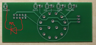
I have a few test boards left that were made with the initial design shown in the attachments of the first post in this thread. They do not have the improvements listed in post #97.
Pictures of these boards are in posts #81 and #98.
The only real problem with these is incorrect wiring of the POWER LED. It can easily be fixed by wiring the LED as shown in the attached picture.
I will give these boards away for free, just for the cost of shipping and parts/assembly if those are wanted. Send me a PM if interested. These boards can be shipped right away.
Attachments
Here is a BOM for connectors and other parts: DAM input board V1.1 BOM (Google sheets)
Hi normundss. Two things. I found for the BOM, the Lorlin Mouser part number for the switch in stock, it is 10WA176
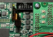
Second, on post 81 what is this small vertical PCB with a green led we can see on the main DAC pcb? Is it standard or a mods you did, see included picture?
Second, on post 81 what is this small vertical PCB with a green led we can see on the main DAC pcb? Is it standard or a mods you did, see included picture?
Attachments
Hi normundss. Two things. I found for the BOM, the Lorlin Mouser part number for the switch in stock, it is 10WA176
Second, on post 81 what is this small vertical PCB with a green led we can see on the main DAC pcb? Is it standard or a mods you did, see included picture?
Thanks, I have updated the BOM.
The vertical PCB is a low noise 3.3V regulator in place of the stock 1117 reg. Not relevant to the input boards at all
")
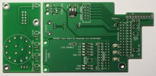
normundss: how long is it from center of pot mount (front board) to the center of the led rows?
Switch to LED center distance is 17.15 mm, if that is what you meant. The volume pot is not mounted on the board, there is a 3 pin connector (JP1) to attach the pot.
Switch to LED center distance is 17.15 mm, if that is what you meant. The volume pot is not mounted on the board, there is a 3 pin connector (JP1) to attach the pot.
Yes, of course i meant rotary switch, not pot. So that distance is 17.15mm
Are the diodes 5 or 3mm footprints?
Also the back board would be nice to have back panel drilling with height and width placement. This to make it possible make cad-files for back panel drilling.
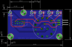
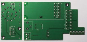
The boards are in and everything looks good. I have built and tested a set, it works and it fits the DAC, which is important considering that I had to eyeball the exact locations of the connectors  Good thing Soren uses standard 2.54mm/0.1" grid, unlike Amanero, which has a strange mix of metric and imperial dimensions.
Attached pictures show front and back of an assembled set. This is what you will get. For kit orders the same parts will be included unassembled.
I will start sending out the orders tomorrow and will continue during the week. The sent orders will be marked as such in Paypal, there will be no additional individual notifications here in the forum.
Good thing Soren uses standard 2.54mm/0.1" grid, unlike Amanero, which has a strange mix of metric and imperial dimensions.Attached pictures show front and back of an assembled set. This is what you will get. For kit orders the same parts will be included unassembled.
I will start sending out the orders tomorrow and will continue during the week. The sent orders will be marked as such in Paypal, there will be no additional individual notifications here in the forum.
Attachments
Yes, of course i meant rotary switch, not pot. So that distance is 17.15mm
Are the diodes 5 or 3mm footprints?
Also the back board would be nice to have back panel drilling with height and width placement. This to make it possible make cad-files for back panel drilling.
The diode pads have standard 2.54mm pitch spacing, you can put in whatever style diodes you like. With the 330 ohm series resistors, the LED current is about 7mA.
I am putting together my own front and back panel drilling files, will post the dimensions soon.
- Home
- Group Buys
- Input and switch boards for Soekris DAM1021 DAC