About TRTOL and related
This value is a 'vertical'-influence (e.g. amplitude related) and not a 'horizontal'-influence (e.g. time related) it seems to me [now] that creating a direct relation between the simulation MAXSTEP and TRTOL is wrong. I do [now] agree to the method used by keantoken, when convergence fails try to vary the TRTOL value and start with a large value (at the least 10 and possibly even 100).
It is important to get a TRTOL value that is as small as possible (down to 1 [and if you like even lower]). When TRTOL ends up being high then you must try to lower the MAXSTEP value, the logic here is: If the MAXSTEP value is low then the 'range' in witch 'p' is expected to fall will be smaller (making it more difficult to converge) but the divergent from the main curve will also be smaller, when (but this will not always be) the divergent is smaller it may be that the possibility that the point 'p' falls within the predicted range is larger.
Especially circuits with high Q values and extreem steep transients will prove to be difficult. When this circuits contain large capacitors and/or inductances try adding 'appropriate' series and parallel resistances to dampen the circuit. Also (if in use) try to lower the dvdt value of the/any signal source in the circuit.
When the simulator can not find a DC-operating point (use the .OP command), vary TRTOL and have a look at the PIVTOL and PIVREL values. The usage of these settings is more a question of [dark] art than exact science (for what I can find )
)
Also note that for AC 'convergence' the values ABSTOL, RELTOL, CHGTOL and VNTOL play a significant role in addition to TRTOL. In my opinion varying TRTOL is a good startong point. As above: The usage of these settings (with the exception of TRTOL) is more a question of [dark] art than exact science (for what I can find)
My main reference for the above is http://www.elettrotecnica.unina.it/files/demagistris/didattica/TdC/SPICE_like_simulation.pdf
This value is a 'vertical'-influence (e.g. amplitude related) and not a 'horizontal'-influence (e.g. time related) it seems to me [now] that creating a direct relation between the simulation MAXSTEP and TRTOL is wrong. I do [now] agree to the method used by keantoken, when convergence fails try to vary the TRTOL value and start with a large value (at the least 10 and possibly even 100).
It is important to get a TRTOL value that is as small as possible (down to 1 [and if you like even lower]). When TRTOL ends up being high then you must try to lower the MAXSTEP value, the logic here is: If the MAXSTEP value is low then the 'range' in witch 'p' is expected to fall will be smaller (making it more difficult to converge) but the divergent from the main curve will also be smaller, when (but this will not always be) the divergent is smaller it may be that the possibility that the point 'p' falls within the predicted range is larger.
Especially circuits with high Q values and extreem steep transients will prove to be difficult. When this circuits contain large capacitors and/or inductances try adding 'appropriate' series and parallel resistances to dampen the circuit. Also (if in use) try to lower the dvdt value of the/any signal source in the circuit.
When the simulator can not find a DC-operating point (use the .OP command), vary TRTOL and have a look at the PIVTOL and PIVREL values. The usage of these settings is more a question of [dark] art than exact science (for what I can find
)Also note that for AC 'convergence' the values ABSTOL, RELTOL, CHGTOL and VNTOL play a significant role in addition to TRTOL. In my opinion varying TRTOL is a good startong point. As above: The usage of these settings (with the exception of TRTOL) is more a question of [dark] art than exact science (for what I can find
)My main reference for the above is http://www.elettrotecnica.unina.it/files/demagistris/didattica/TdC/SPICE_like_simulation.pdf
Last edited:
I have found simulations where a value of 100 was needed and also simulations where a value of 0.001 was needed.
However it should be noted that if reducing TRTOL slows down the simulation, what you are doing is increasing the time resolution in an indirect way, and you would probably get better results just by increasing the resolution the normal way.
However it should be noted that if reducing TRTOL slows down the simulation, what you are doing is increasing the time resolution in an indirect way, and you would probably get better results just by increasing the resolution the normal way.
I have found simulations where a value of 100 was needed and also simulations where a value of 0.001 was needed.
Yes, as in my previous post I agree to your method
However it should be noted that if reducing TRTOL slows down the simulation, what you are doing is increasing the time resolution in an indirect way, and you would probably get better results just by increasing the resolution the normal way.
Yes, TRTOL slows down the simulation due to the fact that the 'vertical'-tolerance (amplitude related) will be smaller and thus more steps are needed. No denying that
[as I explained in the previous post]Also [as explained in the previous post] tinkering with these values should only be done if the simulation is in trouble. If the simulation works and more precision is needed then lower MAXSTEP.
Another way without using a circuit on the schematic:
For a vertical line plot
freq*1.0i
For a horizontal line just plot
freq
And of course you can shift the lines around just like I described by adding or subtracting real or imaginary numbers.
Great! Thanks for the previous few posts on this.
In hindsight, I should have seen that my self. Such is the beauty of hindsight
Jan
Another way without using a circuit on the schematic:
For a vertical line plot
freq*1.0i
For a horizontal line just plot
freq
And of course you can shift the lines around just like I described by adding or subtracting real or imaginary numbers.
Better.
Attachments
FdW, if it sounds like I'm agreeing with you it's because I am. Often I am not making a counterpoint, just adding to the pile for others who are or will read this thread.
Also [as explained in the previous post] tinkering with these values should only be done if the simulation is in trouble. If the simulation works and more precision is needed then lower MAXSTEP.
Well, a common example would be a simulation using 2**12 points. Raising TRTOL to 10 often fixes the noise floor. You can increase the points to 2**13 or 2**14, but your simulation will take 2-4x longer. And there is still a chance you will need to adjust TRTOL anyways. 10-cycle Sine wave THD simulations tend to like TRTOL at default, but change the kind of test you're doing and the needs change.
On most computers 2**14 points is fine, I often go as high as 2**16. So using 2**12 points is usually more speed than I need and I increase it to a comfortable level. But it's important to have the option of using 2**12 points if you need to for a long simulation or one with many parameter steps.
If you need to have a long simulation of say 500 cycles, there is an obvious advantage to finding the right TRTOL value for 2**12 points rather than increasing the number of points until the simulation takes hours to run.
One case where raising the number of points is almost definitely necessary is if you are wanting to see 10MHz oscillation on a 1KHz sine wave. Although in these cases I usually use a 10k or 100k sine wave. I rely more on AC analysis to see whether my circuit will oscillate, occasionally increasing the number of points to check for oscillation in transient analysis.
Last edited:
Any impact of this discussion on FFT tutorial?
Is there any impact on the FFT discussion from post 1270 to 1329 on the FFT tutorial starting at post 19?
In summary, it appears to me that the discussion relates to:
Thanks.
Is there any impact on the FFT discussion from post 1270 to 1329 on the FFT tutorial starting at post 19?
In summary, it appears to me that the discussion relates to:
- scripts for automating the calculation of the required parameters.
- "special" situations in which explicitly setting of less-used parameters might be required.
Thanks.
Generally you will be fine if you set the timestep low enough that the simulation takes a good 5 seconds to run (running smoothly, not jerking forward). If you are looking at <-120db THD then you want to start worrying about simulation settings. There are other situations where it matters as well, for instance measuring nonlinear PSRR or response using a noise input source.
Another case is if you need to run a really long simulation, then adjusting parameters to make the simulation more efficient will keep you from waiting for hours on the simulator.
Another case is if you need to run a really long simulation, then adjusting parameters to make the simulation more efficient will keep you from waiting for hours on the simulator.
@dch53 (and others interested ) Most of the time no (when no 'special' action is needed) the procedures described in post #19 (and on) are fine, maybe the only remark is that the number 262144 (2^18) is a bit high and may slow down your simulation unnecessary.
Reading this https://kenkundert.com/docs/eda+t93-preso.pdf you will find some advice, but there must be an need to do this and more understanding is needed (in most cases) as before, when needed try tinkering with RELTOL and TRTOL first, there is no fixed answer that leeds to predictable results (for any situation, or for most of the problems, or even, for any of your problems [if you have any]).
and
) Most of the time no (when no 'special' action is needed) the procedures described in post #19 (and on) are fine, maybe the only remark is that the number 262144 (2^18) is a bit high and may slow down your simulation unnecessary.Reading this https://kenkundert.com/docs/eda+t93-preso.pdf you will find some advice, but there must be an need to do this and more understanding is needed (in most cases) as before, when needed try tinkering with RELTOL and TRTOL first, there is no fixed answer that leeds to predictable results (for any situation, or for most of the problems, or even, for any of your problems [if you have any
]).Remedies for DC Accuracy Problems
• Assume computed solution is correct
Circuit may have unanticipated problems
Debug circuit as if on lab bench
Circuit may have multiple solutions
Use NODESET to select solution
• Check topology
• Check models
• Check component values
• Check power supplies
• Tighten RELTOL
• Check GMIN
and
Selecting Truncation Error Tolerances
Truncation error tolerances only affect accuracy of transient analysis.
All Newton convergence tolerances are also used as truncation error tolerances. In addition there are the
following parameters.
• TRTOL – relative truncation error tolerance
TRTOL is equivalent to LTERATIO in Spectre.
Sets acceptable truncation error relative to RELTOL
Allows independent control of KCL and truncation errors.
Do not set TRTOL < 2.
In general, if you need more accuracy, tighten RELTOL. Tightening TRTOL is not a good idea
because it causes the simulator to shrink the time step in order to accurately follow the errors that
result from not completely converging the Newton iteration. Generally, TRTOL is used to allow the
Newton criteria to be set much tighter than the truncation error criteria (this is useful when trying to
reduce charge conservation error to negligible levels). Loosening TRTOL by the same factor that
RELTOL is tightened results in the Newton convergence criteria being tightened while keeping the
truncation error criteria the same.
• CHGTOL – absolute charge tolerance
Spectre has no equivalent to CHGTOL.
Should be tightened as devices shrink.
CHGTOL should be set such that roughly CHGTOL = VNTOL × Cmin where Cmin is the smallest
interesting capacitor in the circuit. If you are having problems with trapezoidal-rule ringing, tighten
CHGTOL.
• TMAX – maximum time step
Use if simulator misses events or for onset of oscillation.
Should not normally be used to control error because
1. Convergence criteria not affected.
2. Only shrinks large steps.
In general, tightening RELTOL is a better way to control error than tightening TMAX. TMAX is a
poor way to control error for several reasons. First, tightening TMAX does not tighten the Newton
convergence criteria. Second, tightening TMAX only shrinks large time steps. Thus tightening
TMAX only has an effect when signals are not moving much, and not when signals are moving
rapidly. TMAX is the preferred way to control error if signals are very small compared to their DC
levels. This happens during the build-up phase of an oscillation. In this situation, the signals are
generally too small to produce enough truncation error to shrink the time-step.
• LVLTIM – Time-step control method selection
Can be used to disable truncation error time step control.
This is very dangerous and is not recommended!
Last edited:
Put that in a frame and display it at your local art gallery!.
Hah! Yes there often is beauty in engineering.
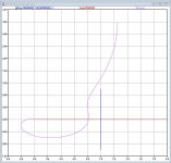
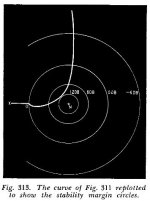
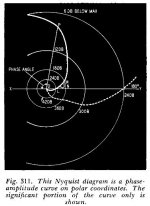
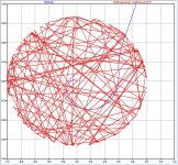
Another one for you if you are bored: How can I plot a circle on the Nyquist plot. Background: A circle can have a diameter corresponding to a certain gain magnitude. If you then draw circles for say 3, 6, 9 etc dB, you can immediately see the gain margin because that is the circle that the curve touches when crossing the real axis. See attached as example (from a 1954 (!) book by Crowhurst).
Jan
Attachments
one more excerpt from https://kenkundert.com/docs/eda+t93-preso.pdf
Remedies for Transient Accuracy Problems
• Check initial operating point.
• Check topology.
• Check models.
• Check component values.
• Check power supplies.
• Check stimulus waveforms.
• Tighten RELTOL.
• Check GMIN.
• If charge conservation problem, use charge-conserving models.
• If point-to-point ringing problem, use Gear’s method.
• If excessive loss, use trapezoidal rule.
• If simulating an oscillator, set TMAX for 10-25 time steps per
period.
Hah! Yes there often is beauty in engineering.
Another one for you if you are bored: How can I plot a circle on the Nyquist plot. Background: A circle can have a diameter corresponding to a certain gain magnitude. If you then draw circles for say 3, 6, 9 etc dB, you can immediately see the gain margin because that is the circle that the curve touches when crossing the real axis. See attached as example (from a 1954 (!) book by Crowhurst).
Jan
As we know, the points on a circle are defined as x = cos(theta) and y = sin(theta) where theta varies from 0 to 2*pi.
In a Nyquist plot x is the real and y is the imaginairy axis.
How do I put this in LTspice??

It would be easy in MatLab...
Jan
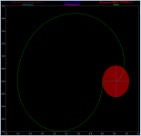
Add this 'sin(frequency)+cos(frequency)*1i'-trace and you will have a circle
But it is opaque, so you should draw it as first and all others will draw on top of it.
If you then select a dark color, it will look fine
But it is opaque, so you should draw it as first and all others will draw on top of it.
If you then select a dark color, it will look fine
Attachments
Last edited:
Time step too small...
Hi. I'm trying to implement your system but must be missing something in the instructions.
I've copied your .options .param and .tran verbatim
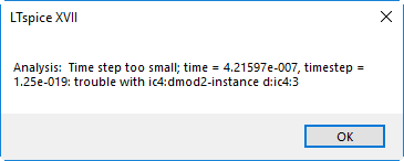
When I run the simulation I get the error message "Time step too small..."
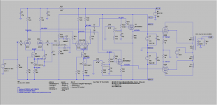
I've attached a screenshot of the error and model. Tried changing the engine to "Alternate" as mention in a posting related to this error but the simulation runs extremely slowly.
Would you be able to take a look please?
Thanks!
Here is what I have come up with to try and consistently get -300db noise floors.
Hi. I'm trying to implement your system but must be missing something in the instructions.
I've copied your .options .param and .tran verbatim
When I run the simulation I get the error message "Time step too small..."
I've attached a screenshot of the error and model. Tried changing the engine to "Alternate" as mention in a posting related to this error but the simulation runs extremely slowly.
Would you be able to take a look please?
Thanks!
Attachments
Last edited:
Hi. I'm trying to implement your system but must be missing something in the instructions.
I've copied your .options .param and .tran verbatim
When I run the simulation I get the error message "Time step too small..."
The problem appears to be that I made the capacitors way too high to correct the FFT as per the tutorial starting at post #19.
Returning them to 0.1uF results in the sort of FFT depicted in the tutorial.
If I try 100uF the sim to runs glacially.
What is the solution here?
Are the same settings appropriate for determination of THD?
Add this 'sin(frequency)+cos(frequency)*1i'-trace and you will have a circle
But it is opaque, so you should draw it as first and all others will draw on top of it.
If you then select a dark color, it will look fine
That's interesting Frans! I realized that a circle would be x = sin(phi) and y =cos(phi) but didn't know where to get the phi. Your use of freq instead puzzles me a lot, but hey, if it works it works!
I'll check it out,
Edit: It gets more and more artsy, special for Anthony...;-)
Jan
Attachments
Last edited:
Resoution to capacitor size issue
While LTSpice is happy with a capacitor value of "0.1u" it isn't happy with "1".
I have found that if I specify my capacitor value as "1F" the simulation runs normally.
The problem appears to be that I made the capacitors way too high to correct the FFT as per the tutorial starting at post #19.
Returning them to 0.1uF results in the sort of FFT depicted in the tutorial.
If I try 100uF the sim to runs glacially.
What is the solution here?
Are the same settings appropriate for determination of THD?
While LTSpice is happy with a capacitor value of "0.1u" it isn't happy with "1".
I have found that if I specify my capacitor value as "1F" the simulation runs normally.
- Home
- Design & Build
- Software Tools
- Installing and using LTspice IV (now including LTXVII), From beginner to advanced