Thank you very much for your explanations! I tried that too, I can see the same numerical results in Spice error log , but i can see the FFT graph too only when i use .four 20000 10 10 V(DIF) where i defined V(DIF) as behavioral . I thank you all! I should look for some time to learn more about simulations.It's much easier to learn this way, when different people show different views on the same matter. I don't have a proper formal education in the electronics , just 18 years of tinkering and stealing bits and pieces of information from here and there...For me , the art electronics is a BIG Puzzle...I think it was named Art of electronics for people like me, unable to grasp the mathematics in it...Incidentally dreamth, something I forgot to mention: you can also use waveform arithmetic in your .four command without needing a behavioural voltage source. For example:
.four 20k 10 8 V(Out1,Out2)
(using your example in post #1833)
I've run into a problem transferring a model over and onto a clean install of LT. I can't understand what is going wrong as I get the same error coming up each time.
The model is one I put together (for an LM3886) ages ago and it has always worked fine when called upon.
So all I have done is copy the model details from the appropriate folders on the working installation and onto the new. Another speaker model that I created and copied in exactly the same way works perfectly, just not the LM3886. What makes it worse is that I'm sure I've done this before without issue.
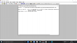
The error is always the same and looks like this. It says 'fatal error missing gain'. I've no idea what all the other stuff is.
The model details all look correct and in the correct place and the B&W703 model that I also copied over in the same way works perfectly.
The model is one I put together (for an LM3886) ages ago and it has always worked fine when called upon.
So all I have done is copy the model details from the appropriate folders on the working installation and onto the new. Another speaker model that I created and copied in exactly the same way works perfectly, just not the LM3886. What makes it worse is that I'm sure I've done this before without issue.
The error is always the same and looks like this. It says 'fatal error missing gain'. I've no idea what all the other stuff is.
The model details all look correct and in the correct place and the B&W703 model that I also copied over in the same way works perfectly.
Attachments


can you share the .asc file for the LM3886? Maybe we'll see something in there???
Looking at the error it looks like you have a comment line wrong, LTSPICE is trying to interpret Linear Technology as a parameter in U1.
tommost
Sure looks like LTSPICE thinks it has found a voltage controlled voltage source (an "E" element) in the netlist. BUT the sixth lexeme on the line, was not a valid entry for the gain of the VCVS
lexeme 1: Ename -- tells LTSPICE this is an E element whose name is name
lexeme 2: nodeOP -- tells LTSPICE the name of the node to which the output (controlled) voltage source's positive terminal is attached
lexeme 3: nodeON -- tells LTSPICE the name of the node to which the output (controlled) voltage source's negative terminal is attached
lexeme 4: nodeCP -- tells LTSPICE the node name of the input (controlling) voltage's positive terminal
lexeme 5: nodeCN -- tells LTSPICE the node name of the input (controlling) voltage's negative terminal
lexeme 6: gain -- tells LTSPICE how much gain you want this element to have. V(nodeOP) - V(nodeON) = gain * [ V(nodeCP) - V(nodeCN) ]
can you share the .asc file for the LM3886? Maybe we'll see something in there???
Here you go... but remember these are simply copied from what was a working installation, I haven't altered anything.
The .asc called 'LM3886v1 plus mute' is a working simulation that the subcircuit was ultimately created from.
The Zipped folders are a copy of he contents of the LM3886v1_1 folder in the earlier post together. The 'Autogenerated' folder contains the .asy files.
Edit... please see post #1851 for details of an error in my base LT model file.
Attachments


.........BUT the sixth lexeme on the line, was not a valid entry for the gain of the VCVS...........
Now that's a word I'd never come across before (lexeme) 🙂
I still haven't figured this out.
This morning I ran the base model of the sim (that works) and is the file labelled LM3886v1 plus mute in the earlier post.
From here I re saved it under a new file name and deleted all the gubbins around it to create a new subcircuit and symbol... and that to gives the same error when I try and use it.
This shows the base circuit does actually work.
Attachments

Thank goodness for Disk imaging...
I have just uninstalled LTspice and reinstalled a version from around June last year. All my files now work correctly. This is a circuit with two LM3886's running in parallel.
I have no idea why or what is going on here. The LM3886 model and symbol files are the same ones, I didn't touch anything in the documents folder part of LT.
Attachments

Fixed 🙂
It seems there are issues (my opinion) with the latest versions of LT. I commented a week or two back in this thread about issues over updating... anyhow the fix was simple.
First I proved that an old version installed onto this Windows installation worked
Now I uninstall the old version and reinstall the latest direct from Analog.com. This fails with the same error as the initial clean install.
All I had to do was run the field update which completed in seconds but it did 'something' because now everything works.
All this and my using the model in another design led me to find an error in the base circuit I used.
I've 'blobbed' a node onto the wrong trace and this error meant the circuit worked OK only as long as the mute pin was tied to the negative rail.
The correct configuration is detailed here. The error (the incorrect file exists in this thread only) has R4 connected to the Mute line and not the rail below it.
Attachments

lib statements
Haven't used ltspice in a while, when I opened it, it asked to update and I did that. So my version is now XVII (x64), Feb 6, 2020 12:26:07 US Pacific. I'm running this on the latest updates in win10 x64.
The problem I'm having is with .lib or .inc statements.
In the control panel I have my directory E:\documents\spice\ added to both the symbol search path and library search path.
My new file I'm creating is in is e:\documents\spice\Draft1.asc
I have the Cordell models in the file e:\documents\spice\KT-Cordell-models.txt
Then in my new file, Draft1.asc, I add a new spice directive and put in .inc KT-Cordell-models.txt and it inserts it on the page.
I insert a transistor. When I right-click the transistor, the transistors listed in the KT-Cordell-models.txt file are not available.
I must be doing something wrong, but I can't recall how to get this to work. I've tried changing the .inc directive to .lib with no luck.
Also, interesting if I right click the .inc directive on the page, it comes up and has the .lib box checked. So I click to check the .inc box, and it changes the statement from .inc to .lib, bizarre. If I change the button selection back to .lib (since it puts that in) and click "ok." It doesn't change it on the page. It's like the editing of the directive doesn't work.
What am I doing wrong?
gabo
I'm afraid I struggle with models and would probably need it in front of me but I would suggest you run the update again manually. Just go to 'Tools' and 'Sync Release'.
I spent a long long time last week looking for a model problem that in the end was caused by clean installing the latest build.
Installing and using LTspice IV (now including LTXVII). From beginner to advanced.
I spent a long long time last week looking for a model problem that in the end was caused by clean installing the latest build.
Installing and using LTspice IV (now including LTXVII). From beginner to advanced.
Thanks Mooly, I did that and it didn't change anything.
I have discovered that even though I get quirky results from the .inc and .lib statements, and when I get them in there the devices don't show up in the list to pick from.
However, if I manually reference them on a device and hit "run" it seems to take the device. It's a bit more of a pain and I'm not sure right now if it's taking all the parameters, but it doesn't give me an error on the device.
I'll keep working on my circuit and eventually be able to discover if it's working correctly.
gabo
Haven't used ltspice in a while, when I opened it, it asked to update and I did that. So my version is now XVII (x64), Feb 6, 2020 12:26:07 US Pacific. I'm running this on the latest updates in win10 x64.
The problem I'm having is with .lib or .inc statements.
In the control panel I have my directory E:\documents\spice\ added to both the symbol search path and library search path.
My new file I'm creating is in is e:\documents\spice\Draft1.asc
I have the Cordell models in the file e:\documents\spice\KT-Cordell-models.txt
Then in my new file, Draft1.asc, I add a new spice directive and put in .inc KT-Cordell-models.txt and it inserts it on the page.
I insert a transistor. When I right-click the transistor, the transistors listed in the KT-Cordell-models.txt file are not available.
I must be doing something wrong, but I can't recall how to get this to work. I've tried changing the .inc directive to .lib with no luck.
Also, interesting if I right click the .inc directive on the page, it comes up and has the .lib box checked. So I click to check the .inc box, and it changes the statement from .inc to .lib, bizarre. If I change the button selection back to .lib (since it puts that in) and click "ok." It doesn't change it on the page. It's like the editing of the directive doesn't work.
What am I doing wrong?
gabo
That's not how .inc files work, the included models don't get added to the choose device dialog box.
My good buddy Gabino Alonso explains it here.
YouTube
tommost
Ah, thanks for that tommost!! That's sort of where I got by hacking around, but was missing one piece. I'm not sure the model I have matches up with the symbol, so I'll let it autogenerate the symbol. It doesn't look as nice, but at least I'll know it's right!
thanks, gabo
thanks, gabo
Thanks again tommost, I am heading out to youtube to watch some TV! haha. My first attempt at modeling a tube amp, my first stage is a simple 12ax7 and now that I have my inc/lib statements sorted and working I'm getting a nasty almost sawtooth wave out of the first 12ax7. Clearly not correct, but it's such a simple circuit I'm not sure what's going on. Maybe my 12ax7 model needs some work.
I'll get it sorted eventually and learn some things along the way, so all good and I am making progress.
gabo
I'll get it sorted eventually and learn some things along the way, so all good and I am making progress.
gabo
Thanks again tommost, I am heading out to youtube to watch some TV! haha. My first attempt at modeling a tube amp, my first stage is a simple 12ax7 and now that I have my inc/lib statements sorted and working I'm getting a nasty almost sawtooth wave out of the first 12ax7. Clearly not correct, but it's such a simple circuit I'm not sure what's going on. Maybe my 12ax7 model needs some work.
I'll get it sorted eventually and learn some things along the way, so all good and I am making progress.
gabo
The way I test a model I'm not familiar with is to set it up in the test circuit given in the device data sheet and see if the results match the measured response graphs. I've never done this with a tube but my *guess* would be that you would vary the grid & plate voltages and plot the plate current you get as a result - kind of a simulated curve tracer.
By the way if you plot the Id vs Vds curves for a variety of Vgs values of many manufacturer's FET models you will see discontinuities in the curves. This always pi$$ed Mike E. off when customers would question LTSPICE's results... "It's the #)$*&#!!! models!!!". The LTSPICE FET models are much more accurate than the ones provided by almost all FET vendors, especially in the ohmic region.
tommost
Very interesting info, thanks for that! I think my tube model is ok. The thing that was causing me problems is... I have a CCS circuit on the cathode of the tube, pulling constant current. But the results I get weren't right, so I replaced the CCS circuit with a CCS component from the component library and dialed in the current I was expecting out of the CCS circuit.
That seems to have resolved my problem. I'll eventually go back and figure out why the CCS circuit isn't working like I expected, but for now that's a minor issue so I'm off to other things.
Thanks again for the help. LTspice is much better than fiddling with components in the shop, especially to try out scenarios until I get something that I might want to try. Then I can go to the shop!
gabo
- Home
- Design & Build
- Software Tools
- Installing and using LTspice IV (now including LTXVII), From beginner to advanced