Anyone can answer my question?. Thanks
If it is ok , then what will be the most used darlington transistor ?.
I think my guess is it is used only on power circuits for motor and stuff.
AlexK.
If it is ok , then what will be the most used darlington transistor ?.
I think my guess is it is used only on power circuits for motor and stuff.
AlexK.
Unsuitable? I think it depends on your requirement or your definition for "suitable".
TIP47 is designed for audio (if I'm not mistaken). It's very common. Of course not in state-of-the-art amplifiers.
The "best" one is probably MJ11012-MJ11016 from Motorola. I knew a circuit that was highly praised by a serious audiophile. I built it and I didn't see any reason why it should've been praised.
MJ11015/16
has been used as an alternative in Pass A40 amp.
has been used as an alternative in Pass A40 amp.
All of the above parts reflect Nelson Pass's original parts list,
with the single exception of the Motorola output transistors (MJ11015 and MJ11016),
though Nelson does recommend these as one possible alternative.
http://www.passdiy.com/howto/part-sub.htm
The Lambda output devices are no longer available, and they weren't that common to begin with. Lambda appears to still be in business, but not in the business of power transistors.
Common everyday complementary power darlington transistors will substitute for these. They need to be rated at 75 watts or higher, 5 amps for higher, and 80 volts or higher.
Good examples of these are the TIP142 (NPN) and TIP147 (PNP), which are currently available from Digikey.
Another fine example, although harder to get, are the Motorola MJ11012, MJ11014, and MJ11016 (NPN) and MJ11013 and MJ11015 (PNP).
palesha said:Jay,
How about putting the circuit here?
Unfortunately I don't have a softcopy. I still have the PCB with one channel still assembled with components. I had a hand drawn of the circuit but because I don't think it is special, I might have lost it.
I have ccts which were not acquired in softcopies or through the internet. I do have interest in seeking comments about the circuits but I don't know who owns the cct so I decided not to post any of them.
built subamp (400w peak),solid punch,used darlington pairs(for output stages).
hooked up on cheapo for 'test'(to see if it plays).now working great to (super)power my sub.quality::cant say,never gave it freq>150hz🙂
hooked up on cheapo for 'test'(to see if it plays).now working great to (super)power my sub.quality::cant say,never gave it freq>150hz🙂
I think that Jfet diff & current mirror + MOSFET SE preamp stage with current source and bias ~150-160mA or more + high current gain (>100) push pull BJT output stage (for example MJL1302/3281) with bias ~ 100mA is the better solution for class AB...
2 stages for voltage amplification + 1 for current.
More stages & open loop gain=more (not only) dynamic distortions...
2 stages for voltage amplification + 1 for current.
More stages & open loop gain=more (not only) dynamic distortions...
They are transistors, and they are connected the same way many amplifiers.
internally, it has two transistors, the first one emitter goes into the second transistor base... both emitter have connection to some amplifier output line....the first one has an emitter resistor internally....there are a protective diode...and the gain is the multiplication result...the product related the first one multiplied the second one.
They are constructed with Silicon...and they are inside the same capsule..... people prefer to use to switch, because fast...will be fast too using to audio.
There are guys that perceive some distortion in trebles.....
Also there are people that use 680 picofarads from base to colector to avoid oscilation...and this destroy the sound.
There are many factories that used, and good brands, despite of those things.
Half Myth and half reality...we need to elect a Mythbuster for us..there are many...thousands myths running there....i am not sure...but darlington beeing bad bad for audio applications may be another myth.
regards,
Carlos
Darlingtons in an EF output stage do not add any more gain (or at least not more than maybe 1-2%, only on account of more Beta being available). Darlington connected BJTs are commonly used in output stages, BUT integrated darlington connected components ('darlington transostors') are not that common. This is not to say they are useless. They are usually robust and quite heavy duty, and have usable characteristics, but care should be taken when using them - only some of them are suitable and in carefully chosen cases.
The problem is in the integrated 'base leak' resistors. These are resistors connected between the E-B junction of the first and second transistors in the pair, and the E of the second transistor.
In discrete amplifiers, these are normally connected between the B-E connection and the output. Note that the output is not the same as the E of the second transistor - normally, there is a low value emitter resistor from it to the output. This, to an extent, bootstraps the built-in base leak resisitor in a darlington power transistor, making it look as if it had a higher value.
The importance of this resistor is, that it sets the bias current of the first transistor in the pair, which is the key in minimizing the crossover area discontinuity with this kind of output stage (note that class A operation of course avoids this problem). There are also other considerations to do with bandwidth, gain droop and switch-off time. In a discrete design you optimize this resistor, but with integrated darlingtons you cannot - you are at the mercy of what is inside the package, and this is usually NOT the right value. Although you can manipulate the effective value of this resistor by chosing the emitter resistor for the whole package, changes in said resistor influence other things - and you can only effectively increase the built-in value - which tends to be too high to begin with. Not all darlington packs are created equal, though. For the reasons above, there were/are a few darlington power packs that had 4 and sometimes 5 pins, for a built-in thermal compensation diode and/or the junction between E and B of the first and second transistor in the pair.
boxedin said:Anyone can answer my question?. Thanks
If it is ok , then what will be the most used darlington transistor ?.
I think my guess is it is used only on power circuits for motor and stuff.
AlexK.
Are darlington pair suitable for audio amplifiers
Yes, they are suitable for audio.
If built and used correctly.
Even if designers not often use 2 transistors in one case,
in fact there are many, many professional amplifiers, using Darlington connected transistors in output stage.
Some also use Triple Darlington Output stages.
Such outputs are made by normal single tansistors, but using same arrangements as Darlington devices.
Myself has not gotten as to be as crazy as using triple darlington configuration,
because that is not my way of doing it 🙂 not yet anyway.
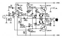
Here is a good example how simple ( few parts ) an amplifier
can be built, using some commonly available and low priced darlington transistors.
An externally hosted image should be here but it was not working when we last tested it.
You can study this interesting amplifier project a bit more here:
http://europa.spaceports.com/~fishbake/amp/ca100.htm
Uses TIP142 + TIP147.
Datsheet from OnSemi ( former Motorola )
http://www.onsemi.com/pub/Collateral/TIP140-D.PDF
lineup
http://lineup.awardspace.com/
National's LM4702 audio driver has an application note (AN-1490) that uses one pair of Darlington's per channel. That note shows a graph with some very low THD+N results. It's too bad there are not more graphs in the app note so we could really see what is going on but this is another example of using darlingtons in audio.
-SL
-SL
Ilimzn explained it the best as usual, Darlington arrangement is quite popular and well suited for audio, but when made with discrete transistors, can be tailored to fit the application. I have seen Darlington package devices used as output stages, but there MUST be adequate thermal compensation when used as EF stage because the Vbe change with temperature will affect both the driver and output transistors since they are in the same package. IMO thermal compensation should always be used with EF output stages. Better bias stability and reliability.😉
Not very good for 3 reasons... see if you can spot them! But, it could be improved quite simply.
Hi all
Agree with comments about Darlingtons. I generally recommend separate drivers/outputs every time. Two "big issues": generally, because Darlingtons have same transistor types in the case, they have a double-rate frequency response fall-off which may make stabilisation more difficult. Or if not stabilisation (if you use simple Miller thingys) then maybe HF distortion.
Also, not much good for power. Safe operating area usually has power roll-off at around 30V. Modern trannys like ON Semi's MJ21193/4 give 80V capability before power roll-off. So if you want a robust amp with lots of watts try separates.
Cheers
John
- Status
- Not open for further replies.
- Home
- Amplifiers
- Solid State
- is darlington pair is unsuitable for audio amplifier?