"Is leakage inductance a measure of how much flux escapes out to the surroundings?".
Is leakage inductance a measure of how much flux escapes out to the surroundings?No, just 120v to 18v, that's all. 160-220va.
Leakage inductance wouldn't be my enemy in this case.
Right now I use Hammonds (they have what I need, easy to buy), they hum a little on their own and they're not constructed well enough so tiny bits of torque on them, ever, creates double the hum forever.
No, I don't see it that way. The flux lines don't line up because the coils are physically displaced (the core helps). The term leakage isn't referring to whether the field is external to the transformer.
to me leakage appears as flux generated by the input winding that does not couple to the output winding.
In my head I see that as escaping, doing no useful work.
So I asked the question: Does it relate in some form to flux that escapes to the surroundings?
In my head I see that as escaping, doing no useful work.
So I asked the question: Does it relate in some form to flux that escapes to the surroundings?
Good question, but say an air cored transformer is used. Much of the flux will appear external to the coils. Does that change due to mutual coupling or does it just appear externally with a different impedance?
You are right to suggest that an air core has a big flux field.
The highest flux is inside the coil.
There is an external flux field and that seems to go out to infinity where it has become infinitely small.
adding a core makes a better job of routing the field and containing most of it within the transformer/coil
So, yes to your second part, it seems intuitive to surmise that the strength/size of the external field is related to what does not couple between the transformer coils.
The Audax hd3p had an air cored transformer to generate the higher voltage required to drive the capacitance of the gold electrodes.
I suspect this transformer has a bigger external field than a metal cored transformer. But air core was good enough for the >6kHz signals.
to me leakage appears as flux generated by the input winding that does not couple to the output winding.
In my head I see that as escaping, doing no useful work.
So I asked the question: Does it relate in some form to flux that escapes to the surroundings?
A good question. I did measure leakage flux for a bunch of transformers a few years back. If I find the data I'll post it. I did show it in the blowtorch thread for anyone crazy enought to try and find it there.
Attached are the measurements from a split core transformer (14A) and an over under (PC). Both Signal transformers. Note the mounting position differences! The PC version flux leakage has much better coupling into the test chassis on other measurements.
My read is that the less the flux coupling the more the leakage but it is directional.
My read is that the less the flux coupling the more the leakage but it is directional.
Attachments

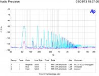
Directional fits with the advice to experiment with rotating a transformer to see if the hum field effect on a nearby circuit can be minimised.Attached are the measurements from a split core transformer (14A) and an over under (PC). Both Signal transformers. Note the mounting position differences! The PC version flux leakage has much better coupling into the test chassis on other measurements.
My read is that the less the flux coupling the more the leakage but it is directional.
Thanks for looking that up.
A nearby steel panel will redirect some of the field to an easier route. That has the effect of reducing the field that does not get rerouted through the adjacent panel.
The original question was
Are we getting closer to an answer? Or do we need a some more transformer expert contribution?Is leakage inductance a measure of how much flux escapes out to the surroundings?
Last edited:
You said that the flux reaches to infinity and that is related to what I am saying as that doesn't change. That is not to say the intensity won't or the impedance seen by an external element tapping into the magnetic circuit.
from
transformer - About "leakage inductance" - Electrical Engineering Stack Exchange
transformer - About "leakage inductance" - Electrical Engineering Stack Exchange
..........First, imagine a core with one winding of N turns. If the winding carries has a voltage V across it, then the flux linked to it Must change at a rate V/N. Now, most (99%) of this flux increase happens through the core, but the rest circulates through the air. The flux (rate) through the air is the leakage component and can be modelled as a bulk leakage inductance.
The way I try to think of leakage flux is, if you remove the core of the trafo, what would the field of the windings look like? You can think of the air as the second core of any winding. Toroidal trafos reduce leakage so well because all windings completely enclose the same air core. But the air cores of split-bobbin trafo windings are far apart and hardly touch at all.
Similarly, trafos with all windings on the same bobbin have less leakage than split-bobbin trafos and the windings loosely share the air core. But in this case, unlike a toroid the air core is not fully enclosed within the coils, but expands out from the edges of the bobbin straight into space. So in this case the windings have less leakage than a split-bobbin trafo, but some of the radiated flux is actually non-leakage flux, unlike the split-bobbin trafo. Another way to look at it is that if you remove the core of a single-bobbin trafo, it becomes an air-core trafo. It radiates a lot of flux, even though most of that flux isn't leakage flux.
So leakage inductance doesn't always have a direct relationship with the radiated field of a transformer, although I think there is a strong correlation. And the directionality of the field throws a wrench into the idea that the trafo with the least leakage inductance would be the most magnetically silent in any given application.
No. That can be shown with two counterexamples:Is leakage inductance a measure of how much flux escapes out to the surroundings?
Take two toroidal windings, let's say in air to simplify matters, but the core material is irrelevant.
No matter how you arrange those windings, the coupling will be zero (if they are properly made), because the external flux is zero. Thus, the leakage inductance of such an arrangement will be maximal, equal to the inductance of the winding.
In summary: zero leakage flux/high leakage inductance.
Now, wind two twisted wires in a loop or a ring, trying to arrange the turns as randomly as possible inside the ring.
The leakage inductance of such a construction will be almost zero, because of the strong coupling, but practically all of the flux leaks through the surrounding air.
In summary, maximum leakage flux/low leakage inductance.
In the toroids example, you can vary the coupling (and the leakage inductance) if you allow the toroids to interpenetrate, but the outside leakage flux will always remain =0
No. That can be shown with two counterexamples:
Take two toroidal windings, let's say in air to simplify matters, but the core material is irrelevant.
No matter how you arrange those windings, the coupling will be zero (if they are properly made), because the external flux is zero. Thus, the leakage inductance of such an arrangement will be maximal, equal to the inductance of the winding.
In summary: zero leakage flux/high leakage inductance.
Now, wind two twisted wires in a loop or a ring, trying to arrange the turns as randomly as possible inside the ring.
The leakage inductance of such a construction will be almost zero, because of the strong coupling, but practically all of the flux leaks through the surrounding air.
In summary, maximum leakage flux/low leakage inductance.
In the toroids example, you can vary the coupling (and the leakage inductance) if you allow the toroids to interpenetrate, but the outside leakage flux will always remain =0
This seems to be a quite good example to me.
Another example are flyback transformers fitted with a fluxband to minimize leakage field. This fluxband does not help reducing stray inductance.
To answer the question - the assumption that leakage field correlates to stray inductance may be true under certain restricting conditions, but not as a general rule.
Leakage Inductance is just a model, an "equavalent circuit" comprising of an ideal transformer (coupling factor = 1) and an impedance in series with the primary that yields the same effective primary inductance reading (with secondary shorted) as the real part. And it's not a true inductance as it depends on frequency with eddy losses at work etc.
Leakage inductance is a measure of how much flux generated by one winding fails to link to another winding. 'Escaping' may not be a useful picture to use.AndrewT said:Is leakage inductance a measure of how much flux escapes out to the surroundings?
to me leakage appears as flux generated by the input winding that does not couple to the output winding.
In my head I see that as escaping, doing no useful work.
So I asked the question: Does it relate in some form to flux that escapes to the surroundings?
Since you asked it twice 🙂 : no, it´s not or related to "what escapes to surroundings".
To expand on this:
agree that the word "leakage" to name it may be misleading, in my view was poorly chosen, but hey, we have what we have 🙄
It gives the impression that "energy is sent to load or transformer and somehow leaves it in a lossy way" ; but if that were so, it would be modelled in parallel with the load, which is not the case.
Look at it this way:
1) transformer windings have high inductance, or to be more precise, high enough so its impedance is way higher than load impedance, at any frequency of interest.
2) so it would pass very little current when you apply a voltage, since self impedance is so high, BUT a second winding is coupled to it, and connected to a load.
If such load is resistive, it is "reflected" to primary, again as a resistive load, and inductance gets canceled.
Resistive load is on secondary, yet it appears "as if" the proper scaled resistive load were at the primary, and in parallel with primary inductance, practically shorting and cancelling it.
Carrying the analysis to the extreme, *shorting* the secondary should fully kill/cancel primary inductance, any measurement on the primary coil should show zero inductance ... yet we know it never does, there is always some remaining inductance.
To better understand the concept: IF that inductance were in parallel with the load, it would be cancelled by the short, because "anything in parallel with a short measures as a short" so for it to remain we must conclude that it´s some kind of *series* inductance ... as KSTR (and others) said.
To see it from nother point, "leakage" gives you the impression that some energy is sent to the load and lost , "because it goes somewhere else" ("surroundings") while in fact it´s not allowed to get there in the first place, blocked by series inductance.
Personally, I´d much prefer to call it "remaining inductance" 🙂
EDIT: agree with DF96:
'Escaping' may not be a useful picture to use.
Last edited:
'Escaping' may not be a useful picture to use.
stranded in the primary perhaps....?
- Status
- Not open for further replies.
- Home
- Design & Build
- Parts
- "Is leakage inductance a measure of how much flux escapes out to the surroundings?".