I recently acquired an old Yorkville 100B bass amp. I was cleaning the pots and accidentally shorted the amp when a stray string end from the peghead of the guitar on my lap swept across the exposed circuit board. Stupid, I know.
I now get no sound when I plug the guitar in to the input. When I plug in to the effects return I get normal sound, but of course my only volume and tone control is at the guitar. Based on this I'm assuming that the power amp section is ok, but the problem is in the preamp.
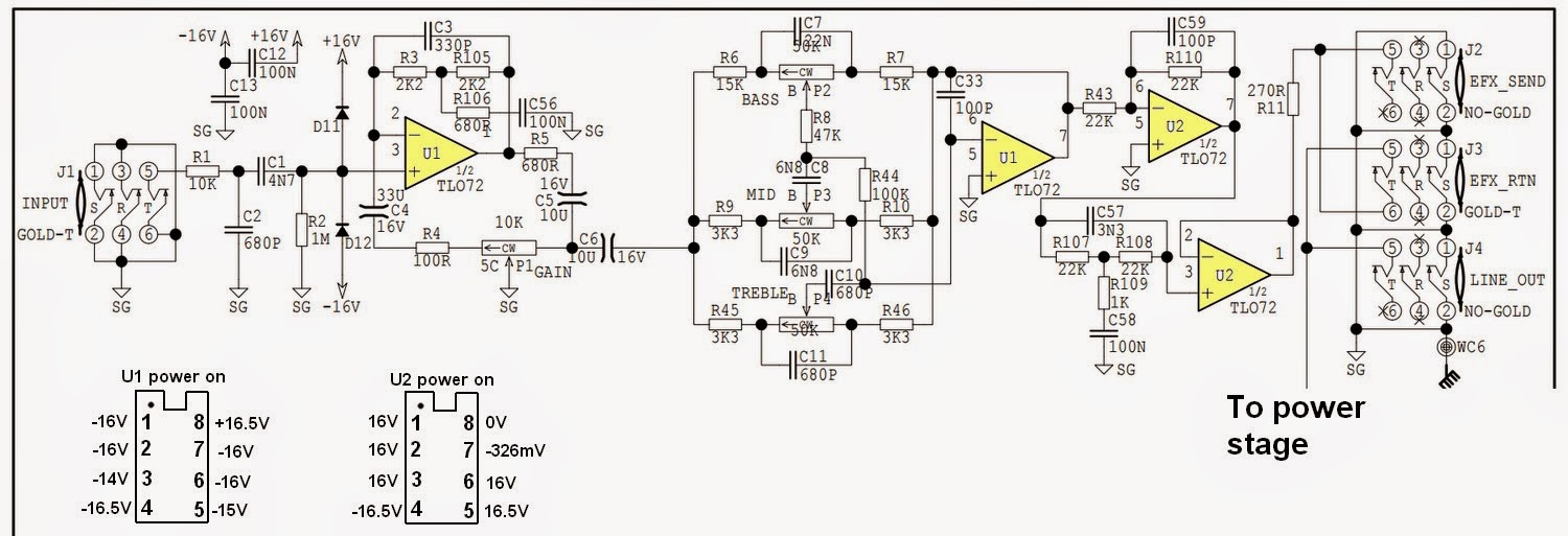
The service manual shows that the preamp has two TL072 op amps and based on my reading I thought these might be the most prone to failure following a short.
I don't have an oscilloscope so I checked the input end of the preamp circuit with a multimeter. With the amp unpowered, but with my guitar plugged in to the bass input, I strummed the guitar and checked AC voltage at C1 and also at pin 3 (input) of the TL072 (part of the schematic is posted below). In both locations the voltage jumped up to 0.15V after a hard strum and decayed down to 0.002V over time. I checked the AC at pin 1 (output) of the Tl072 and got nothing after a hard strum. From my forum reading I expected a functioning op amp would show AC at the output even with the power off. I powered up the amp and went through the same tests and got the same results: AC at C1 and the TL072 input, but no AC at the TL072 output.
I think this means that the TL072 is not functioning correctly. Am I on the right track? This preamp section has a second TL072 associated with the tone controls. I can't test the signal at that second op amp because the signal is blocked earlier in the circuit. What's the likelihood that the short also cooked the second op amp?
Thanks for our help.

I now get no sound when I plug the guitar in to the input. When I plug in to the effects return I get normal sound, but of course my only volume and tone control is at the guitar. Based on this I'm assuming that the power amp section is ok, but the problem is in the preamp.
The service manual shows that the preamp has two TL072 op amps and based on my reading I thought these might be the most prone to failure following a short.
I don't have an oscilloscope so I checked the input end of the preamp circuit with a multimeter. With the amp unpowered, but with my guitar plugged in to the bass input, I strummed the guitar and checked AC voltage at C1 and also at pin 3 (input) of the TL072 (part of the schematic is posted below). In both locations the voltage jumped up to 0.15V after a hard strum and decayed down to 0.002V over time. I checked the AC at pin 1 (output) of the Tl072 and got nothing after a hard strum. From my forum reading I expected a functioning op amp would show AC at the output even with the power off. I powered up the amp and went through the same tests and got the same results: AC at C1 and the TL072 input, but no AC at the TL072 output.
I think this means that the TL072 is not functioning correctly. Am I on the right track? This preamp section has a second TL072 associated with the tone controls. I can't test the signal at that second op amp because the signal is blocked earlier in the circuit. What's the likelihood that the short also cooked the second op amp?
Thanks for our help.
What's the likelihood that the short also cooked the second op amp?
With coupling caps at the input and output of each stage, any problems should be isolated to one stage.
These are dual op amps though, so both stages may be in the same package.
Last edited:
Have you checked DC on the output? If it's near one of the rails, the OP is probably toast.
You might as well install a better part while you're at it. Maybe a TLE2072, which makes a pretty good improved '072 replacement. A low-Ib bipolar should actually work quite well, too (NJM4560, BA4560, NJM4565, or even NJM4556 if its current draw is not a concern; note that parts employing bias current compensation trickery do not qualify, e.g. LM4562 - their current noise is much higher, yielding higher noise levels when source impedance is high, which it is here).
You might as well install a better part while you're at it. Maybe a TLE2072, which makes a pretty good improved '072 replacement. A low-Ib bipolar should actually work quite well, too (NJM4560, BA4560, NJM4565, or even NJM4556 if its current draw is not a concern; note that parts employing bias current compensation trickery do not qualify, e.g. LM4562 - their current noise is much higher, yielding higher noise levels when source impedance is high, which it is here).
Last edited:
I have the same problem with my joe meeck mc2 compressor, pre-amp , noise gate. It's full with tl072 and not too well caps. But it has a vintage non-linear sound which makes it fun too use, only the noise level is too high . I seldom use it, only when i'm playing with my synth and midicontroller(akai mpd26) and ofcourse my desktop and soundcards ain't the issue. If i scratch or just play a record with the mc2 sidechained for the bass, you hear the noise increase if i increase the amount of signal through the mc2.
I have to say that i never have tried a regulated voltage source , instead of the chong-psu, but a better opamp which ain't too expensive(a lot of opamp) it is worth to dry.
thx richard
I have to say that i never have tried a regulated voltage source , instead of the chong-psu, but a better opamp which ain't too expensive(a lot of opamp) it is worth to dry.
thx richard
With guitar equipment a finger on the end of the connecting lead can act as a signal generator. It will hum like mad if the circuit is OK.
What are the voltages at pins 8 and 4? I expect these would be +16 volts and -16 volts respectively. The IC pins are close together and so if your guitar string bridged a gap between either of these two and any other of the pins even momentarily then the affected half of your TL072 will be caput.
It seems the illustrated section performs a fuzz box function where the input signal will be clipped by D11 and D12 if the voltage exceeds + or - 0.6 volts and that is the section that has failed. In that case you are going to need to change the TL072. If my fuzz box supposition is correct the agenda is one of the guitar overdriving the input and D11 and D12 clipping the top off the waveform so the TL072 can handle the thus restricted input level. I would stick with that part since that is what the manufacturer used and his agenda appears to have been to create a musical experience from his equipment which is different from hi-fidelity sound reproduction.
In replacing the TL072 you should check D11 and D12 for integrity with the diode setting on your meter once the old part has been removed from the board.
Last edited:
mjona -
The voltages are indeed +16V (pin 4) and -16V (pin 8). In fact, all pins on U1 are roughly -16V except pin 8 at +16V.
I've attached the full schematic for the preamp showing other side of U1 and both sides of U2. The image also shows the voltages at each pin with the amp powered on. I suspect U2 is also damaged, or at least half of it is damaged based on the +16V at Pin 1 output.
This is a bass amp with no effects - just a clean signal with bass/mid/treble controls. I'm still on the steep part of the learning curve and I couldn't really figure out the function of diodes 11 & 12.
In my limited experience, the inputs and outputs of op amps in music systems should all be about zero, the middle of the power supply rails. This means 2, 3 and 1 should all be about zero. Those you should be able to measure with a dVM DC scale.
I've found DVM AC scales to produce random numbers on music. An exception is the Fluke 177 apparently, but it only goes to 1.5 khz whereas music goes way above that. If you can't afford a scope and want to trace AC (music) through a system I find an analog VOM with a 2.5 VAC scale to be useful in these early stages. Once you get to the transistor buffer areas you need a 20 VAC or 50 VAC scales. I use a Simpson 260-6XLPM meter, they still sell Simpson 280s now.
But many problems are DC, expecially after a burnout. For those a garden variety Sears (non autoranging) DVM is useful.
Diodes 11 and 12 are designed to keep the input from the amp from going outside the range of the power supplies and blowing something up. Say you plugged the output of a 1.3 kw PA amp into the input of the bass amp, that was supposed to go to the speaker, boom, toast, and resistor R1 will probably vaporize and save the rest of the circuit. Thats what happened (I conjector) on my CS800s PA amp, the input resistors were toast. Bet R1 is a tenth watt or eighth watt resistor, they make really cheap "fuses". All those 1/4 phone plugs floating around on stage in the dark, fans or amateurs as roadies, all sorts of things could get plugged in the wrong hole.
After my PV1.3k blew up, I had some rice grain sized 100n 50v caps blown up, that kept my op amps from working. Just saying. I just changed the **** things, until it started working, but some DVM's do have a usable capacitance scale, up to about 10 uf anyway. Mine were in the power supply, but I did have one 400 pf cap blown up, and you've got several small disk caps sprinkled through this. The resistors, if you take the op amps out of the sockets, you can measure them with any old DVM. I had a lot of those blown up too. Those ceramic caps, I salvaged most of what I needed out of old blown up PCAT power supplies, the diodes were useful too. I would use the e-caps out of a PCAT power supply only at the front in the middle of a war, the e-caps in those $17 power supplies are trash grade.
Last edited:
mjona -
The voltages are indeed +16V (pin 4) and -16V (pin 8). In fact, all pins on U1 are roughly -16V except pin 8 at +16V.
I've attached the full schematic for the preamp showing other side of U1 and both sides of U2. The image also shows the voltages at each pin with the amp powered on. I suspect U2 is also damaged, or at least half of it is damaged based on the +16V at Pin 1 output.
This is a bass amp with no effects - just a clean signal with bass/mid/treble controls. I'm still on the steep part of the learning curve and I couldn't really figure out the function of diodes 11 & 12.
Pins 4 and 8 on U1 are the power supply pins and the voltages you have quoted for those are in order.
The observations in Indianajo's post #8 clarify the purpose of D11 and D12 and I too would expect the voltages on the input and output pins to be zero (within a few millivolts). Since that is not the case U1 is suspect and you should remove this from the board and measure the voltages at pin 3 to see if this is zero or not and measure the pin voltages for U2 again.
I would suggest soldering a turned pin 8 pin socket in the IC footprint on the printed circuit board with the notch at one end matching the outline of the overlay. If pin 3 is zero in that situation then you can plug in a replacement TL072. If not then you will need to look at the voltage drop across D11 and D12.
I see there are a few 16 volt electrolytic capacitors in the signal lines. These would be suspect if the voltage presented under the present fault conditions is the opposite to what it should be. The negative side of electrolytic caps will be in the image of a bar with a row of - symbols inside the bar.
I have never had to do this, but it might be worth checking the current into/out of the power pins.
Add a 100r to the power feed of both pins and measure the quiescent voltage drop.
It should tally with the datasheet.
Add a 100r to the power feed of both pins and measure the quiescent voltage drop.
It should tally with the datasheet.
Having checked data manuals for TL072 National Semiconductor and Motorola I see from the latter the maximum allowable voltage on the input pins must not exceed the +/- rail voltages or 15 volts, whichever is less.
The relevant pin numbers are 2 and 3 for one individual amplifier and numbers 5 and 6 for the other. The only reading in that range is -14 volts on pin 3 in U1, the readings on all others in U1 and U2 are in breach of the specification. In the case of pin 3 in U1 the source of the -14 volts can be internal to U1 or D12 instead of blocking the negative rail is dropping 14 volts against the grain. Try the diode test range on your meter in both directions - it should work in one direction only.
I would expect the voltage at pin 8 on U2 to be +16.5 volts the same as on pin 8 in U1. You might check the continuity of voltage from J8 on the printed circuit board in case the track has burned out somewhere between that point and pin 8 on U2.
IC failure might account for the strange voltages but you still need to do some detective work before replacing these.
Last edited:
I'd also pull the U1 IC and check for almost rail voltage on all the pins of the socket after it is gone. If so I'd check other things, like the decoupler caps. Reading good at 2v with the capacitance function of the meter doesn't mean they will still hold off 15v in real life. Those rice grain 100nf caps sprinkled around op amps are just as fragile as the IC, and invisible on the print because they are just power supply decoupler caps. No voltage suffix letter after the "104" or "225" means A voltage or 25 or 50v, which makes them fragile. I changed a bunch of them before I found the one (or more) causing my problems. Like I say old switcher power supplies are full of them you can salvage, or you can buy 100 at $.06 each or something from a distributor.
Last edited:
U1 pin 3 cannot reach -14 V except from internal cicuitry of the IC. U1 is suspicious.
Gajanan Phadte
Gajanan Phadte
I have never had to do this, but it might be worth checking the current into/out of the power pins.
Add a 100r to the power feed of both pins and measure the quiescent voltage drop.
It should tally with the datasheet.
The supply current (ID) per amplifier ranges between 1.4 m.a. and 2.5 m.a. (Motorola) less with increasing temperature.
something is broken !The supply current (ID) per amplifier ranges between 1.4 m.a. and 2.5 m.a. (Motorola) less with increasing temperature.
there is no exit route for current into the +ve pin, other than out through the -ve pin.
There is no ground pin. The +ve and -ve quiescent currents should be the same.
Look at the datasheet simple sch.
At quiescent all the signal pins should have zero currents in/out.
Try the diode test range on your meter in both directions - it should work in one direction only.
...
You might check the continuity of voltage from J8 on the printed circuit board in case the track has burned out somewhere between that point and pin 8 on U2.
Using the diode function on the multimeter with U1 in place I found that for both D11 and D12 when the black lead was on the cathode (banded) end I read about 0.6V with power off or power on. Reversing the leads I got 0. Does this suggest that the diodes are working correctly or in this situation with U1 in place are they not be challenged with the 16V potential? I also noted that when I touched the leads to either diode the speaker crackled which probably means nothing, but I thought I'd mention it.
I have continuity from J8 to pin 8 on U2. I don't see J8 on the schematic but it certainly was there on the circuitboard. What do those "J" wires represent? Are they there to facilitate testing?
Observation - schematic shows pin 5 on both ICs as connected to ground, while your measurements are +16 and -15 volts - looks like you may have opened a track - check the traces on the boards.
Usually backwards diodes read 1999 or ---- on ohms but with the power supply in the circuit, you have to charge the main caps up with the ohms scale of the meter to get there, which takes forever. Do not test with the ohms scale of the meter with the power on. And if the main caps are charged up from the power being on, tests with the ohms scale of the meter will be invalid. If I'm going to test ohms, first I use 2000 mv to see if there is any stored voltage on the two points. With the volts scale, the two clamp diodes should read about 15 v across them powered up because they shouldn't conduct unless a big honkin' 48 VAC PA amp output is plugged in the input.Using the diode function on the multimeter with U1 in place I found that for both D11 and D12 when the black lead was on the cathode (banded) end I read about 0.6V with power off or power on. Reversing the leads I got 0. Does this suggest that the diodes are working correctly or in this situation with U1 in place are they not be challenged with the 16V potential?
We can't comment on J8 if it is not on the schematic. If it comes from the output of the op amp and goes to the panel, it's function is usually the "out" of an amp, where the music going in the input can be echoed to another amp or mixer without loading down the guitar pickup.
Using the diode function on the multimeter with U1 in place I found that for both D11 and D12 when the black lead was on the cathode (banded) end I read about 0.6V with power off or power on. Reversing the leads I got 0. Does this suggest that the diodes are working correctly or in this situation with U1 in place are they not be challenged with the 16V potential? I also noted that when I touched the leads to either diode the speaker crackled which probably means nothing, but I thought I'd mention it.
I have continuity from J8 to pin 8 on U2. I don't see J8 on the schematic but it certainly was there on the circuitboard. What do those "J" wires represent? Are they there to facilitate testing?
The tests indicate D11 and D12 are not causing the problem. J8 is a wire link on the component side of the board that jumps over traces underneath the board.
My concern was how is it possible to get a zero volt reading on U2 pin 8 when J8 provides a parallel supply route from C27 to U1 pin 8 where the voltage is + 16.5 volts. The thought was that U2 had fused internally causing a short or a trace had burned out.
Your tests rule out the latter, for now looking into the power supply arrangement in the service manual, I see it is based on zener diodes and paralleled 2k7 resistors which would limit the current able to be drawn and provide protection against short circuiting the rails anywhere.
It would be interesting to know how much current is being drawn from the positive rail through U2 pin 8 and while you could fit a 100R resistor in series as has been suggested by Andrew T, and, from measuring the voltage drop deduce the current drawn by Ohms law, you might get some indication of that in more convenient way.
In a small package like a TL072 the ability to dissipate heat is very limited whereas excess current draw will increase the temperature on the body of the device.
Since the circuit voltages are low, it is safe enough to try the moistened finger touch test to feel how hot U2 is in relation to U1. If you have a temperature probe for your meter you can get a precise measurement.
The moistened finger touch test can also be used for possible heat issues with other components such as electrolytic capacitors and resistors. It is also useful to test for drafts around window seals in the house.
Last edited:
- Status
- Not open for further replies.
- Home
- Amplifiers
- Solid State
- Is this TL072 op amp dead?