Hello,
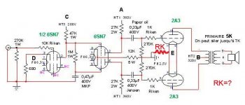
I'm interested by the J.E. Labs 2A3 PP 8W Class A amplifier we can see at http://www.angela.com/catalog/how-to/JE_Labs/PP_2A3/
But I don't like the alternative for 2A3 heaters, I think that AC give too much noise. So I think to build this amp but with DC for heaters.
Does somebody know how to modify this schematic for that ?
I think to use just a 1000V 8A bridge rectifier and 40000µF capacitor. But in this case, what is the best value for cathode resistor ?
Thanks.
Pascal.
Attachments

Re: J.E. Labs psu
hey,
where is the noise going to come from with the AC heaters??? the nature of a pp circuit will largely cancel any hum from the heaters...
dave
PTSOUNDLAB said:But I don't like the alternative for 2A3 heaters, I think that AC give too much noise. So I think to build this amp but with DC for heaters.
Does somebody know how to modify this schematic for that ?
I think to use just a 1000V 8A bridge rectifier and 40000µF capacitor. But in this case, what is the best value for cathode resistor ?
[/B]
hey,
where is the noise going to come from with the AC heaters??? the nature of a pp circuit will largely cancel any hum from the heaters...
dave
Are you sure about that power supply?
The HT supply looks like a misdrawn voltage doubler to me, in which case it would develop 1075V from a 380-0-380V transformer.
If you bridge rectify 2.5V and apply the output to a capacitor, you will not get 2.5V. It takes quite a bit of calculation to work out what you will actually get, but it will be affected by:
Two diode drops.
Capacitor charging to peak AC voltage.
Ripple voltage.
Once it has been juggled to give the correct heating effect, you will have a waveform with lots of higher harmonics due to rectification instead of a 50Hz fundamental. You certainly wouldn't need a 1000V rectifier. Some 20V 10A (for stereo) Schottky diodes connected as a bridge would do the job perfectly well. I'd stick with AC...
2A3 filaments
Hello,
Dave excuse me but my english is not good and I speak about filament and I don't know if in english you say filament to or heater.
EC8010, I'm not sure about the schematic, I have found it on the net at angela instrument, and it's why I speak about it here, for having opinions. I think that a +/- for filament it's better and it's why I have tried to modify it. I have notice in my experience that using a +/- for filament reduce noise/hum.
I have two KBPC806 and 807 and it's why I think of them, of course diode rectifier could be better.
I'm interested by the original schematic, but i am suspicious with filaments, 6SN7 and 2A3 use AC, and all amplifiers I have ear have less hum/noise with DC. It's why I try to have experts opinions.
Cordialement.
Pascal.
Attachments

With push pull you connect the two 2a3's heaters exactly the same, that is if the ov connection from the filament transformer is on the left pin of one valve it must also go to the left pin of the other valve. In this way any noise induced is cancelled because each valve is in opposite phase. The amount of cancellation depends on how well the valves are matched.
The first stage may ebnefit from dc heating, but I wouldn't bother. Why don't you try it with ac and then change your plans accordingly?
Your cathode resistor is 400 ohms.
Why not use the cheaper but equally good (if not better) 6J5 for stage one?
The first stage may ebnefit from dc heating, but I wouldn't bother. Why don't you try it with ac and then change your plans accordingly?
Your cathode resistor is 400 ohms.
Why not use the cheaper but equally good (if not better) 6J5 for stage one?

new psu
Thank you very much EC8010.
I think I will try to build this amp, and it's why I will try to have good and expert opinions before.
Thanks.
Best Regards.
"Cordialement" (in french 😉.
Pascal.
Thank you very much EC8010.
I think I will try to build this amp, and it's why I will try to have good and expert opinions before.
Thanks.
Best Regards.
"Cordialement" (in french 😉.
Pascal.
I would suggest using more than a 8 amp bridge for the filaments.
2 tubes * 2.5a each = 5a.
but, at turn-on they are going to pull way more than 2.5A each.. so use a LV high current bridge.. something like 50v 20A or whatever
(unless silicon rectifiers can handle a 10 - 20s overload? i dont believe so..)
2 tubes * 2.5a each = 5a.
but, at turn-on they are going to pull way more than 2.5A each.. so use a LV high current bridge.. something like 50v 20A or whatever
(unless silicon rectifiers can handle a 10 - 20s overload? i dont believe so..)
It took a while to find the thermal coefficient of electrical conductivity for tungsten, but I persevered (0.0045 per C). If we assume that the filament temperature rises by 800C, then the hot resistance of tungsten is 4.6 times that of its cold resistance. Or, for our purposes, the instantaneous current at cold switch-on will be 4.6 times the operating current = 11.5A per valve. So Colt45 is right. 20A, or perhaps 25A, rated diodes (or a bridge) are required for a pair of 2A3.
But the 2A3 doesn't have a tungsten filament...
Still it does draw considerably more current while heating up.
How much more I don't know.
Still it does draw considerably more current while heating up.
How much more I don't know.
It's probably that as well because the emissive properties of thoriated tungsten were discovered by accident. (The lightbulb manufacturers added thorium to make tungsten easier to draw into a wire.) However, even if RCA hadn't said so on their 2A3 data sheet, you could deduce that the emissive surface is an oxide coating from the operating temperature. Pure tungsten is dazzling white, thoriated tungsten yellow, and oxide coated red.
- Status
- Not open for further replies.
- Home
- Amplifiers
- Tubes / Valves
- J.E. Labs 2A3