Thanks a lot Dave for all these informations.Personally ,I lack the expertise to make good use of them and I'll stop here.Maybe someone else will continue.
In this case you don't need expertise, only a PC with Windows and installing WinPCD. If you unzip the files provided into a new folder C:\Jamo_D830 and run WinPCD, you can open the provided session file (OEM - Minimum-Phase Files) and it will load everything needed into WinPCD. Then you can modify values or change the crossover fairly easily rather than speculate as how changes to crossover values will change the response. If you want to do a bit more than that, there are a couple of simple changes to make (order of the crossover, etc.), but those are easily made. No expertise is required.
Dave
Dave
I struggled to get WinPCD working, probably because the learning curve is too steep for a quick hack here.
But I did import the FRD (minimum phase) and ZMA files into Boxsim without any difficulty apart from having to rename a file as .zma rather than ZMA.
That one was dreadful, TBH. The 4.7mH based notch did next to nothing. The tweeter circuit is an underdamped disaster.
My idea of the bigger coil and quieter tweeter did exactly what I expected.
I looked up the SEAS W18E001: E0018-08S W18E001
5kHz notch needed. 4.7uF and 0.22mH. The supplied Dave's FRD puts the Jamo speaker breakup at 4kHz.
I'm trusting the modelling here. I like the 4kHz notch, which gets a 6.8uF and a 2.2R resistor. Another LCR does good things at 1.3kHz.
Here's my final circuit suggestion with a little vagueness on tweeter level. Interestingly, the 1R and 4.7uF does next to nothing. Most of the rolloff comes from the driver. Dotted is the Jamo original circuit response.
Not wildly different from the original. But better I think. It particularly addresses the awkward lump at 1.3Khz. And I do think a crossover notch should be optimally damped whether it's 4.7uF or 6.8uF based. Gets the phase aligned better.
Attachments


Last edited:
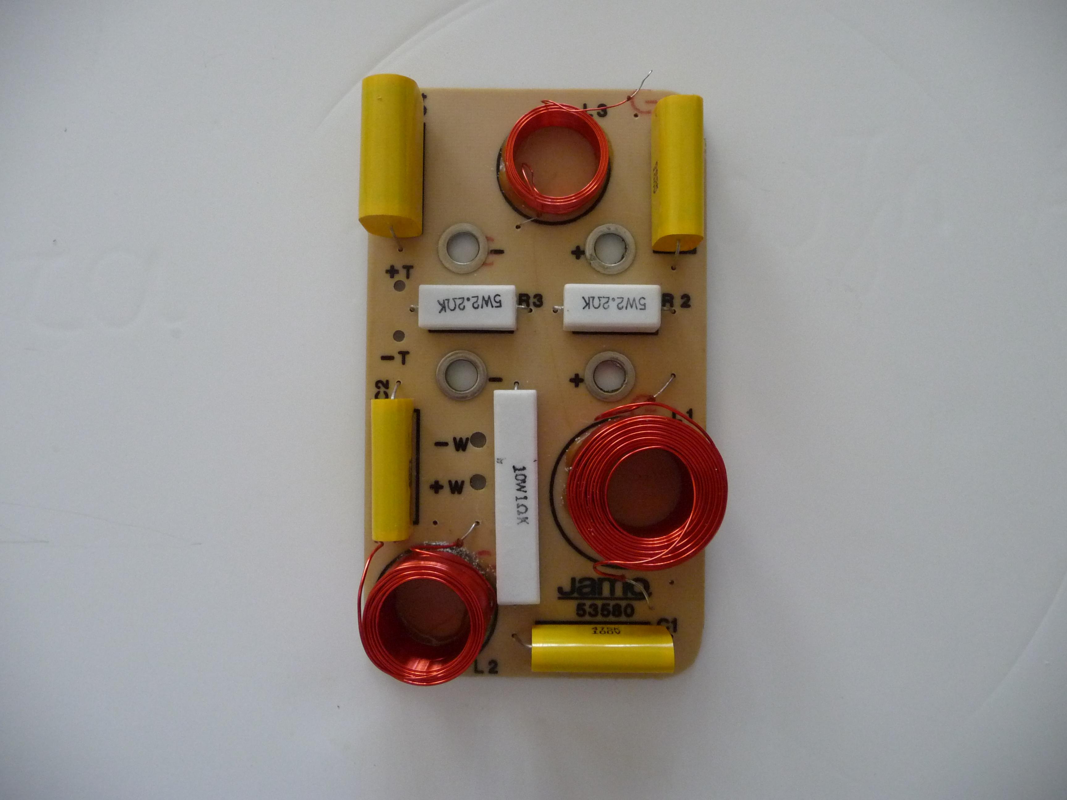
Good morning Steve.A nice job you did,and there are a few details I want to discuss.1)The 4.7mH has an 2 ohm resistance ,that should be added to the 10R of the notch.2)The 1mH coil has a big R in dc ,more than 1 ohm,thus changing the Qts of the woofer and I was reluctant to deal with it.3)What stand for the lower black and dot line in your simulation? 4)Could you run another simulation of the high pass increasing the coil to .33mH and the 10μF cap to13-14? I attach also a photo of the crossover.
P.S.I can't believe that the circuit I presented is t-h-a-t bad!
Attachments

Last edited:
Very tidy crossover there:
I've hit a bit of a problem here. Dave's frd file seems to be inaccurate. The bump should be around 900Hz. The breakup at 5kHz. 😕
It bears little resemblance to the SEAS W18EX001-8. I don't think 4 ohms will fix that.
I don't know what to think right now. There is a lot of guesswork in what we do.
This speaker is really a poor man's SEAS Thor which has 4 ohm bass because it's a Butterworth3 parallel MTM. The notch with the small magnet W18E001 is at 4.5kHz. But the crossover is instructive. Not dissimilar to the Jamo Concert 8.
Trust me on the original tweeter filter, it's OK as it is. Your latest 10uF/0.33mH/12R one drops to 2 ohms in places. It's underdamped. The SEAS Zobel idea is quite good on a tamer sound IMO and just a simple add-on. As it goes, your bass filter looks a lot better in light of the frd file problems.
The SEAS Thor and Odin were always considered thin on bass. Tweeter level adjust is easy, of course. The Jamo is considered overly bright, isn't it?
Attachments


It's not inaccurate. It's actual measurement. I've attached the unmodified far-field measurement windowed for the environment.I've hit a bit of a problem here. Dave's frd file seems to be inaccurate. The bump should be around 900Hz. The breakup at 5kHz. 😕
The W17 was an early version of this type of driver. It does have serious breakup issues. Using SoundEasy's digital filter, I auditioned many crossovers. It requires an Fc no higher than 1800Hz to suit me and even then I still wasn't satisfied. It's a difficult driver to work with.It bears little resemblance to the SEAS W18EX001-8. I don't think 4 ohms will fix that.
If you can make measurements, guesswork can be removed. But you then have to experiment by actually listening to crossover attempts.I don't know what to think right now. There is a lot of guesswork in what we do.
Dave
Attachments

That's good news then, Dave. We can trust the modelling. Thanks for getting back. 😀
I've always hated 6" bass, it just doesn't play nicely with simple filters.
planet10 rustled up an improved SEAS Thor crossover. I ran with that a bit. The Boxsim optimiser is very good at this sort of thing if you point it in the right direction.
Looks OK to me. I really like 4th order networks and use them myself, and this works out very LR4. And has a nice impedance and good driver control.
I wouldn't go crazy on expensive components here. Some compact 70V NP Mundorfs would do for some of the big capacitor values and keep the building difficulty down. But it promises a lot, IMO.
Attachments


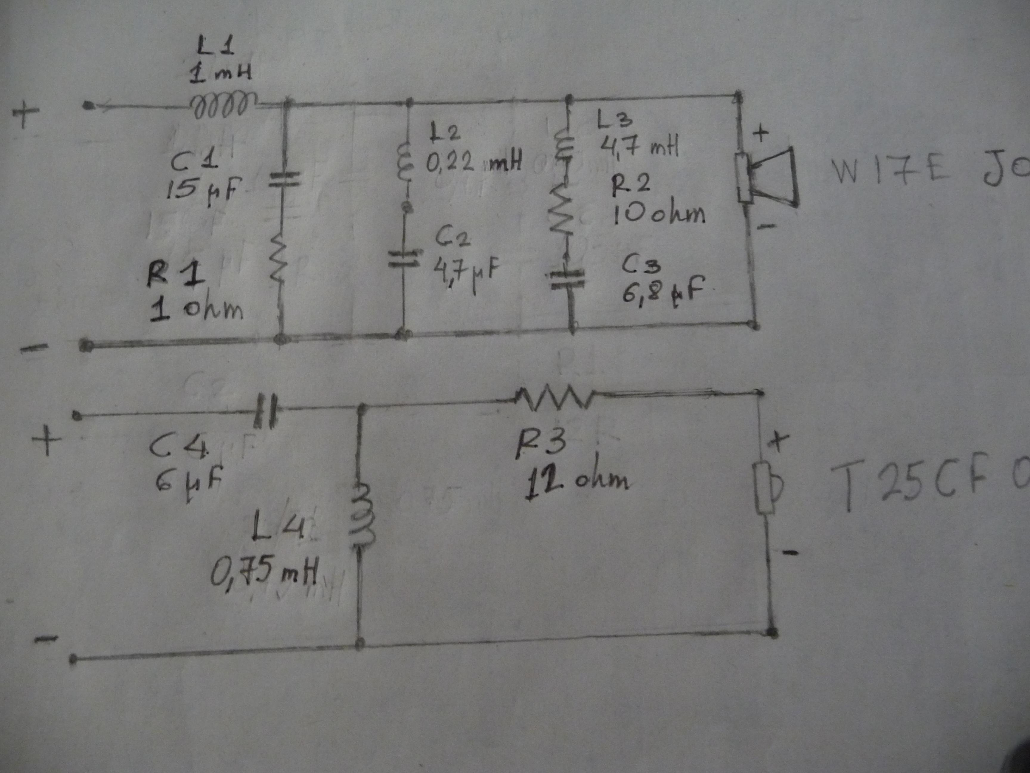
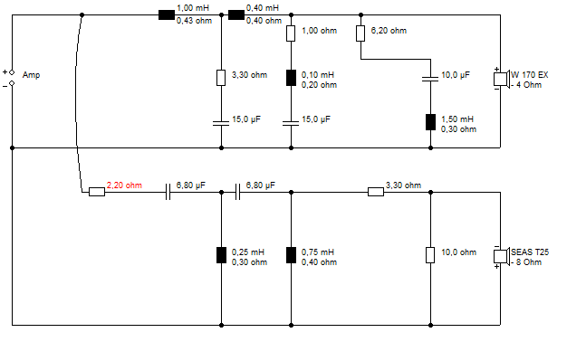
Steve and Dave, you went to great lengths to help me and for that I am truly grateful.I'll try the low pass crossover suggested by Steve in his last post(#48) and in the high pass the original Jamo's crossover with slightly altered values,to reach 2000Hz Fc,as in the schematic(it's the speaker on top)
Steve,I noticed that you mark T25 cf001 as 8 ohm,whereas it is 6 ohm.Is it of any importance?
Steve,I noticed that you mark T25 cf001 as 8 ohm,whereas it is 6 ohm.Is it of any importance?
Attachments

Last edited:
I found a third order tweeter was not so nice with fourth order bass. But don't let me stop you. 😀
I use 8 ohms nominal as a conventional label. They are usually 6 ohms DC resistance and the sim knows this.
The dotted line in the original sim might show what the filter is doing in the original Jamo Concert 8:
Not pretty, is it? I would call that a flawed speaker.
The second redesign I came up with is carefully modelled based on Dave's frd. It's actually regular 4th order stuff, with an added 4kHz notch for the breakup and a 1.3kHz notch for the typical surround resonance. I'm not too sure about exact tweeter level, but it's adjustable anyway.
If it works, I think it'll sound good. I could have got the tweeter flatter, but it messed up the lovely impedance, and it will be fine off axis, IMO. But hey, it's all the hobby. And a hobby is, by definition, an interesting waste of time! 😀
You can always get Boxsim from Visaton. I have a vague idea what I am doing when I import frd and zma files, but there's nothing like doing it yourself.
Last edited:
[Your latest 10uF/0.33mH/12R one drops to 2 ohms in places.] by System7.
No,no.I meant changes on the original Jamo third order crossover schematic ,Steve.About thin sound ,you may check out post #30,there is a link to D.B.Keele's comprehensive test of Concert8.Frequency responce (in anechoic chamber!)is especially revealing.
Last edited:
I'll try the low pass crossover suggested by Steve in his last post(#48) and in the high pass the original Jamo's crossover with slightly altered values,to reach 2000Hz Fc,as in the schematic(it's the speaker on top)
Model this first. A big part of what "makes" a speaker is driver integration. If you cobble together sections from different designs (untested/unsimulated), you are taking a risk.
Kimon is doing some sort of modelling here, but I'm not sure what... 😀
I just ran this one up the flagpole in Boxsim, and I must have the patience of a Saint:
Software | Visaton
Not pretty.
I just ran this one up the flagpole in Boxsim, and I must have the patience of a Saint:
Software | Visaton
Not pretty.
Attachments

Well,Steve, μακάριοι οι πραείς,ότι αυτοί κληρονομήσουσιν την γήν/blessed the meek for they will inherit the earth (Matthew 5:5).
Last edited:
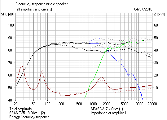
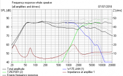
OEM System Measurements
For reference here are the system measurements with the OEM crossover before any modifications. I later modified the tweeter for the top end problem and added felt between the drivers to reduce tweeter diffraction caused by the nearby midwoofer.
Look closely at the summed response. At 1m on the tweeter axis, these show the the midwoofer breakup is not nearly down enough as it affects the summed response to beyond 10K.
Dave
Attachments


Last edited:
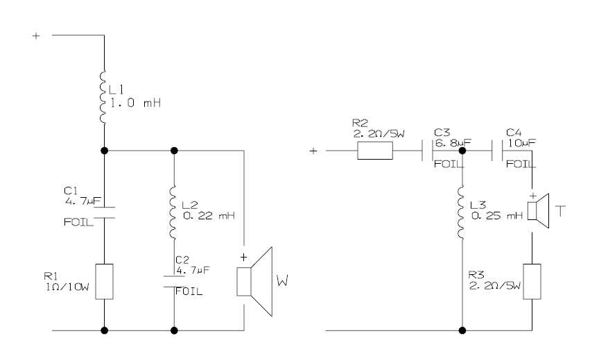
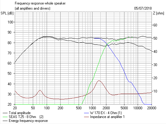
If someone wants to try his luck in a crossover modification, I have attached a project file for Boxsim, fully setup to my best knowing. 🙂
The result of the original crossover is very similar in Boxsim and in my own simulation program (see attached screenshots). Just set the number of frequencies in Boxsim to 599 to avoid excessive smoothing.
Thanks to Dave for providing the data files.
The result of the original crossover is very similar in Boxsim and in my own simulation program (see attached screenshots). Just set the number of frequencies in Boxsim to 599 to avoid excessive smoothing.
Thanks to Dave for providing the data files.
Attachments


Good work, Dissi. I enjoyed seeing someone elses take on importing files into Boxsim.
I think we have discovered some things here about the wretched (a deserved accolade...LOL) Jamo speaker.
The worst goof is the breakup notch. It should be 4kHz 6.8uF/0.22mH/2.2R not 5kHz 4.7uF/0.22mH.
We decided it lacked bass and was overly bright at the top. I never cease to amaze myself, but my original fix seems to work, aside the notch problem which we didn't know about at the time. 😎
The 1.3kHz notch we looked at later seems to be superfluous with a bigger bafflestep coil, so some simplification of any improved filter might be in order but I'm all simmed out right now.
This is amusing. I get into terrible trouble when I say "Woofers are woofers and tweeters are tweeters, and seen one you've seen them all. So don't waste money on Ebay on ancient replacements. Just get something new that fits, and adjust tweeter level."
But it turns out to be true! Here's the sims of the Jamo construction alongside the Default Boxsim project. I just gave the Jamo the Visaton crossover to compare.
So remember: When you laugh at the monkeys in the Zoo, they are probably laughing at you! 😀
I think we have discovered some things here about the wretched (a deserved accolade...LOL) Jamo speaker.
The worst goof is the breakup notch. It should be 4kHz 6.8uF/0.22mH/2.2R not 5kHz 4.7uF/0.22mH.
We decided it lacked bass and was overly bright at the top. I never cease to amaze myself, but my original fix seems to work, aside the notch problem which we didn't know about at the time. 😎
system7 said:I'd think you need to increase 1mH to about 1.5mH and reduce the first simple R1/C1 shunt to 1R and 2.2uF. That should increase the downward bassmid slope. R2 then increases from 2.2R to about 4.7R for about 3dB tweeter level reduction. Simple as that.
The 1.3kHz notch we looked at later seems to be superfluous with a bigger bafflestep coil, so some simplification of any improved filter might be in order but I'm all simmed out right now.
This is amusing. I get into terrible trouble when I say "Woofers are woofers and tweeters are tweeters, and seen one you've seen them all. So don't waste money on Ebay on ancient replacements. Just get something new that fits, and adjust tweeter level."
But it turns out to be true! Here's the sims of the Jamo construction alongside the Default Boxsim project. I just gave the Jamo the Visaton crossover to compare.
So remember: When you laugh at the monkeys in the Zoo, they are probably laughing at you! 😀
Attachments

kimon, I think I have come to some conclusions here.
This speaker is quite similar to the SEAS Thor:
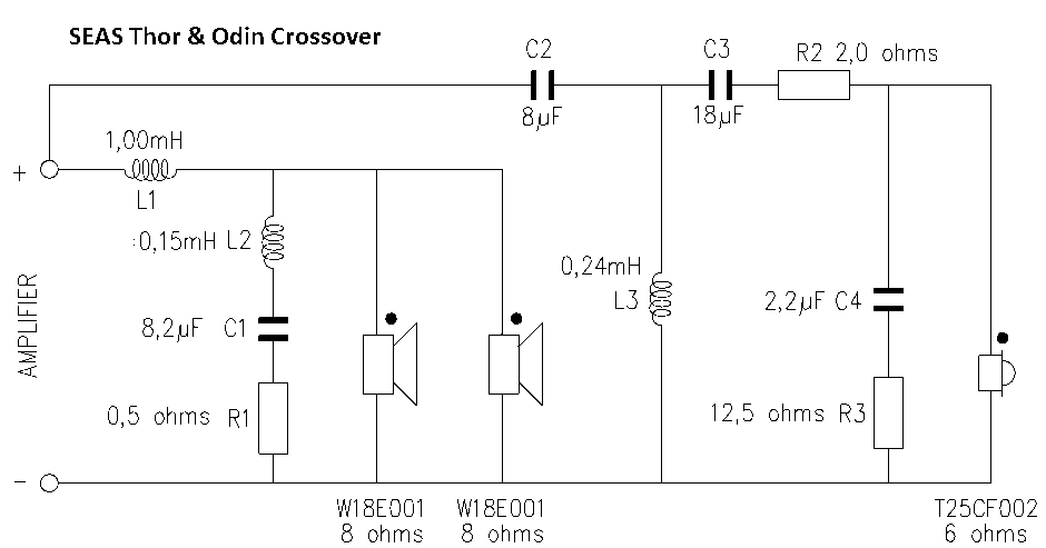
Which is a BW3 MTM design by Joe D'Appolito which is sometimes criticised for light bass, IIRC.
This might just be a bass voicing problem, dependent on room size and placement. The SEAS Thor could be easily adjusted, IMO.
We have discovered the Jamo has a badly designed notch. That is fixed easily enough with two new components, 2.2R and 6.8uF. The voicing is adjusted for more bass with a 1.5mH coil for more slope and a 4.7R resistor to take tweeter down. 1R and 4,7uF doesn't do much, so we'll leave them. Finally, the T25 tweeter is bright at the top, so I like Joe's 12R/2.2uF zobel.
It all comes together as below. If you fix the notch and add the zobel, the voicing change can, of course, be tested on the biwireable connections externally with an additional 0.5mH and a 2.7R. The dotted line is your original as best we can sim it. Not too radical a change, really, and easily implemented I reckon..
This speaker is quite similar to the SEAS Thor:
Which is a BW3 MTM design by Joe D'Appolito which is sometimes criticised for light bass, IIRC.
This might just be a bass voicing problem, dependent on room size and placement. The SEAS Thor could be easily adjusted, IMO.
We have discovered the Jamo has a badly designed notch. That is fixed easily enough with two new components, 2.2R and 6.8uF. The voicing is adjusted for more bass with a 1.5mH coil for more slope and a 4.7R resistor to take tweeter down. 1R and 4,7uF doesn't do much, so we'll leave them. Finally, the T25 tweeter is bright at the top, so I like Joe's 12R/2.2uF zobel.
It all comes together as below. If you fix the notch and add the zobel, the voicing change can, of course, be tested on the biwireable connections externally with an additional 0.5mH and a 2.7R. The dotted line is your original as best we can sim it. Not too radical a change, really, and easily implemented I reckon..
Attachments


Very nice suggestion ,Steve,and remarkably simple.Thanks to Dissi I also spent some time using Boxsim in simulations and I think I'm close to a decision.Many thanks to all of you for supporting me in this quest.
I noticed that you suggest L1 with resistance reduced to 0.5 ohm.Don't you think this will affect bass responce?
I also spent some time using Boxsim in simulations and I think I'm close to a decision.Many thanks to all of you for supporting me in this quest.I noticed that you suggest L1 with resistance reduced to 0.5 ohm.Don't you think this will affect bass responce?
Last edited:
This might just be a bass voicing problem, dependent on room size and placement. The SEAS Thor could be easily adjusted, IMO.
There is an actual problem with the original Thor crossover (too bright/too little bass). Later DIY revisions fixed it.
- Home
- Loudspeakers
- Multi-Way
- Jamo D830 (Concert 8) crossover