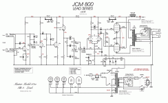
Hello to the forum … in a little while I will finish my project with the 18watt Phoenix (dr Z carmen ghia). I am waiting for some things to come to me and I even thought of getting ready for the next project which will be Marshall jcm 800 2204… I have some questions and I would like someone who knows to help me. first of all I would like to explain that this project will be very high gain than the factory one, that is, I will use some mods that I found .. but beyond that I have the following questions:
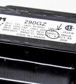
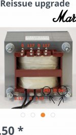
1) transformer high voltage wires . I have seen several schematics which differ from the high voltage ones. some are 650 vac some are 640 vac some are 690 vac and some 694 vac .. which of all is the right one for high gain?
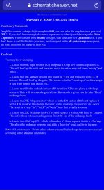
2) about mods . I found this page on web for Marshall jcm 800 2204 mods . And I don’t understand the 1st of mod that say : 1. Locate the 68K input resistor (R3) and place a 330pf 1kv ceramic cap across it. This will beef up the mids and lows and make the entire amp feel more "meaty" and "thick".
I don’t understand that : and place a 330pf 1kv ceramic cap across it,, it’s mean parallel with R3 or after R3?
For now I have only these questions .. thank you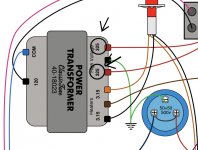


I actually have an early 80s JCM 800 2204! It's the combo model. I love it! So wish you lots of luck.
1. Higher voltages do not really translate to higher gain. So picking between 640 or 690VAC is a bit of a redherring. You just want the highest quality transformer you can buy for your budget, and the closest it matches the specification the less tweeking you will have to do. So just stick to stock here and invest your high-gain creativity elsewhere.
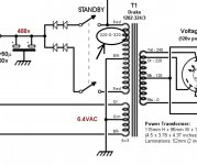
2. It means in parallel, see C2 in the circuit. Also shown is the original frequency response of the stage in green and modified with the capacitor in blue. This allows very high frequencies (above audio) to bypass the grid stopper resistor and arrive at grid. Take care with the mod! See below.
- Ceramic capacitors are, in general, a bad fit for audio, they can be microphonic and capacitance values can drift quite a bit with a DC is applied. Also, there is no need for a component to be rated for 2kV here!
- I would do this with a standard poly. film capacitor.
- Relative to the original response there is a subtle 0.5dB reduction in highs starting from 2.5kHz until around 10kHz. So this will make the bass and mids more pronounced. There is your meaty-ness!
- However, there is a flat response from 10kHz to 100kHz and beyond!
- One of the purposes of the 68k grid stopper resistors to to combine with the input capacitance of the valve and cut these high-frequencies.
- Provided these inaudible frequencies are cut elsewhere you might be OK, but inaudible high-frequencies are generally bad news in guitar amps.
Attachments
Oh thank you , very nice post .. may for this mod with cap across the R3 I use switch , nice by the way . Something other : what capacitors use for jcm800 ? Polyester or polypropylene ? And one last ..do you know about <lenz amplification mod> ? I send to him to learn about the mod of jcm800 but he doesn’t answer me .. do you know about those mods on jcm 800 ?
MODS - edilenzs Webseite!
MODS - edilenzs Webseite!
Last edited:
2. It means in parallel, see C2 in the circuit. Also shown is the original frequency response of the stage in green and modified with the capacitor in blue. This allows very high frequencies (above audio) to bypass the grid stopper resistor and arrive at grid. Take care with the mod! See below.
- Ceramic capacitors are, in general, a bad fit for audio, they can be microphonic and capacitance values can drift quite a bit with a DC is applied. Also, there is no need for a component to be rated for 2kV here!
- I would do this with a standard poly. film capacitor.
- Relative to the original response there is a subtle 0.5dB reduction in highs starting from 2.5kHz until around 10kHz. So this will make the bass and mids more pronounced. There is your meaty-ness!
- However, there is a flat response from 10kHz to 100kHz and beyond!
- One of the purposes of the 68k grid stopper resistors to to combine with the input capacitance of the valve and cut these high-frequencies.
- Provided these inaudible frequencies are cut elsewhere you might be OK, but inaudible high-frequencies are generally bad news in guitar amps.
I understood the instructions in the last attachement in post #1 like you did (the 330 pF capacitor 'across' the 68K resistor means parallel to the 68K resistor) but the instructions also state that this modification "will beef up mids and lows". Looking at your simulation it mainly beefs up the (very) highs. I do see that in your simulation the blue line dips a bit under the green line from about 1KHz to 10KHz but the difference amounts to less than 2 dB. I can hardly believe that this would create the effect of beefing up the mids and lows (which than would be caused by having to set the volume a tiny bit higher to hear a tone of let's say 2KHz at the same level compared to the setting of the volume without the modification in place). So as far as I can see, the modification doesn't do what it is supposed to do.
Last edited:
I interpret the plot as giving the perception of "beefing up lows and mids" but cutting highs. It's basically a shelving EQ on the input. Yeah, it is subtle and might even be pointless! Just trying help OP understand what it actually does.
This isn't the right section of the forum for guitar amps.
Those mods are all quite old and no more used.
I'd work on voltages rather than changing components, etc...
400 to 440 V for B+, 180 to 250V on the preamp (two 10k in series between screens and PI). This is usually a good starting point for standard Marshalls of that era.
Those mods are all quite old and no more used.
I'd work on voltages rather than changing components, etc...
400 to 440 V for B+, 180 to 250V on the preamp (two 10k in series between screens and PI). This is usually a good starting point for standard Marshalls of that era.
what capacitors use for jcm800 ? Polyester or polypropylene ?
Don't know you are familiar with Merlin Blencowe's books but in Designing Valve Preamps for Guitar and Bass he gives a good overview of component types. In summary, I'd pick Polypropylene over Polyester.
But why not get both types and see if you can actually hear the difference. I doubt it's possible if both are close to specification.
I will tell you why I say that. I am from Athens, Greece and here there are not many types of spare parts, I know that polyester capacitors are needed, but in the shops here they do not have 400 volt rated polyester capacitors, the ones that have are only polypropylene for 400 volt rated ..
Prepare a bill of materials and buy everything from tube-town.
They are in EU, so no extra taxes on shown prices.
They are in EU, so no extra taxes on shown prices.
I am looking for passive spare parts for the jcm 800 .. the problem is that in carbon film there are no variations. I have searched in tube amp doctor and musikding.de… the resistors I find in poikilia are metal film .. do they do the same job or do they change the sound?
Metal film are better, lower noise, better temperature coefficient. I'm not a believer in mojo from vintage components 😉
what capacitors use for jcm800 ? Polyester or polypropylene ?
Most vintage amps (and plenty of new guitar amps) use Polyester.
TCD
Metal film are better, lower noise, better temperature coefficient. I'm not a believer in mojo from vintage components 😉
I must admit a lot of the best sounding amps of the thousands that have been across the bench were full of Mylar caps and CC resistors... but plenty weren't.
Guitar amps are like baking a cake, everything makes a difference, some things a lot more than others. 🙂
TCD
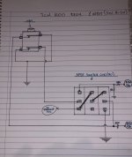
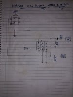
Also I drawing the one input with hi-lo switch .. 🙂View attachment 977899
A few suggestions,
- Ditch the hi / low sensitivity IP, just use hi. You were indicating a high gain
'800 so the low sensitivity IP will likely never be used. I know of virtually no
one who use that IP on an 800
- Ditch the 68k IP resistor feeding V1. Use a 2k right at IP socket with 68p to
Gnd for RF atten, then a 1k soldered into valve socket for grid stopper.
The 68k just adds more noise than the self noise of V1.
- 800's can sound bright or 'glassy' at lower gain settings due to the gain
control bypass cap. Use a 1meg pull switch pot and connect the cap to switch
for 'pull bright' function. Very useful, especially for SC pickups.
- Be very careful adding low end or lower mids to the signal pre distortion
section. The distortion character can suffer greatly becoming loose and
uncontrolled. This is a very tricky knife edge that is part and parcel of guitar
amp design. Only your ears can decide.
- WRT HT voltage: I would recommend lower rather than higher for a few
reasons. a/ An amp with HT around 400 to 450 will be generally more
reliable than one that is pushing 480 and more.
b/ By running a lower HT around 400 or so you can bias the OP tubes into
more class A which usually just sounds more open / better.
c/ Also remember that the HT will also depend on loading Vs transformer
sag. A transformer with lower winding resistance will sag less when tubes are
biased up than one with higher WR.
TCD
And you've got to have a quick look at RobRobinette's notes on these amps.
It explains the circuit (and a few related models) in detail and has some notes on tweaking them.
It explains the circuit (and a few related models) in detail and has some notes on tweaking them.
Also I drawing the one input with hi-lo switch .. 🙂View attachment 977899
This is wrong 😀 … I made it again the hi-lo switch …tha it’s work perfect 👍
- Home
- Live Sound
- Instruments and Amps
- Jcm 800 2204 Marshall + mods
