Thank you spookydd. Your files are much appreciated.
I will still need to modify the board files just a bit for my particular application. (err, really its my son's speaker cabs I built for him that he requested 🙄).
Yes, yes, I know that is NOT the type of wood to use. His future upgrade that he will be doing will be to use double 11/16" plywood for a total thickness of ~1.5".
I had to help with doing the horn math and of course dad's limited budget $$$.
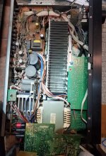
I have 6 amps to build for his, (3 per cabinet) and 1 for my Klipsch 10" sub (internal smps went whacko and fried part of the all-in-1 amp-psu board.)
I have all small parts and drivers to stuff 10 Leach Amps total 😀.
Where the mods will be made will be to a separate OPT board to make use of the 4 donated NOS failed stereo units with good OPT's and HS's (1 6chan, 1 5chan & 2 2chan) with 2 more 2chan working units (Sony, JVC) that I will dismantle and repurpose.
Plus his upgrades will need buy larger trafos, proper heatsinks and all new OPT's.
I will still need to modify the board files just a bit for my particular application. (err, really its my son's speaker cabs I built for him that he requested 🙄).
Yes, yes, I know that is NOT the type of wood to use. His future upgrade that he will be doing will be to use double 11/16" plywood for a total thickness of ~1.5".
I had to help with doing the horn math and of course dad's limited budget $$$.
I have 6 amps to build for his, (3 per cabinet) and 1 for my Klipsch 10" sub (internal smps went whacko and fried part of the all-in-1 amp-psu board.)
I have all small parts and drivers to stuff 10 Leach Amps total 😀.
Where the mods will be made will be to a separate OPT board to make use of the 4 donated NOS failed stereo units with good OPT's and HS's (1 6chan, 1 5chan & 2 2chan) with 2 more 2chan working units (Sony, JVC) that I will dismantle and repurpose.
Plus his upgrades will need buy larger trafos, proper heatsinks and all new OPT's.
Attachments


Last edited:
files
Searched my usb discs and found a lot Jens/Leach files. I place the files for my boards and a newer version.
Maybe usefull .
Good luck, Loek
Searched my usb discs and found a lot Jens/Leach files. I place the files for my boards and a newer version.
Maybe usefull .
Good luck, Loek
Attachments
-
Leachver209.05.SCH.pdf194 KB · Views: 271
-
Leachver208.85.TOP.pdf819.1 KB · Views: 216
-
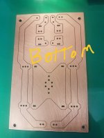
Leachver208.85.BOT.pdf844.5 KB · Views: 218
-
Leach_ver_7.4.6_Top_Mirrored.pdf480.1 KB · Views: 216
-
Leach_ver_7.4.6_Silk.pdf196.7 KB · Views: 285
-
Leach_ver_7.4.6_Sch.pdf149.3 KB · Views: 267
-
Leach_ver_7.4.6_Bottom_mirrored.pdf473.4 KB · Views: 200
-
leach_ver_7.4.6_BOM.pdf72.4 KB · Views: 279
-
Leach_ver_7.4.6.zip303.5 KB · Views: 225
Last edited:

Few posts before spookydd upload the files for the 5 pairs version.
Spookydd have send me the files few months before so i make an order to a pcb factory.i have 2 pairs left if someone interested.
Hi Vasillis, I am interested in 1 pair - PM sent
John
Few posts before spookydd upload the files for the 5 pairs version.
Spookydd hi!
What modifications have you done if compared to Jens design?
I see you designed a better thermal sensing board, anything else?
Are all the parts and values the same?
What modifications have you done if compared to Jens design?
I see you designed a better thermal sensing board, anything else?
Are all the parts and values the same?
Most of the parts are the same and most of the names as well, so the BOM from Jens mostly applies.
But I did tweak a few details besides that more reactive thermal sensing bit.
His BOM calls for 0.47ohms emitter resistors, which I lowered to 0.22 and so the protection network values have been tweaked accordingly.
I changed the values for the input coupling caps and feedback ones, plus added protection diodes on the feedback caps.
The huge feedback cap is doable because it doesn't need to be high voltage and with the protection diodes on it, there is no way even in a fault situation that it would be exposed to more than the drop across the diodes, both ways.
I have 1000uF for the input coupling cap, and 4700uF for the feedback return.
That's how we clean up distortion below about 1khz nicely.
I recreated it according to the 5 pairs version Jens called 5.6.10, but also implemented one more small change that was discussed back then but didn't make it into that revision of it, which is to tap the feedback all the way at the actual output, on the L//R device.
A few layout tweaks here and there to fit the few extra parts and make enough room for the larger ones, nothing major.
I will revise this again real soon, with more tweaks, like removing those fuses, thinking about adding SSRs, adding a way to have a separate front end supply, separate the L//R combo into 2 devices, so the resistor can be radial as well as the air coil.
I will also add the resistor to the protection network to have a second slope, as this also didn't make it into that revision.
He made one little mistake on that 5.6.10 version that was later corrected, which is to insert the resistors in the supply rails between the pre-drivers and drivers, but it should be ahead of the pre-drivers.
It's still the leach amp, still for the most part about the same as what Jens did for v5.6.10, with few minor changes..
I did some 3D stuff and CAD for it, to make it easier to build. Lots of details to read.
One thing worth mentioning about using a BOM to build an amp, is that some values can change depending on the chosen rail voltage. Not to mention possibly choosing different devices as well.
So I feel it might be better to make a BOM with values for different rail voltages..
So I feel it might be better to make a BOM with values for different rail voltages..
My PM box now fixed.
also to be clear as i receive few PMs asking info about the boards.
i am currently building a pair with exactly the Jens bom
BR
Vasilis
also to be clear as i receive few PMs asking info about the boards.
i am currently building a pair with exactly the Jens bom
BR
Vasilis
Great! I might build one.Here is one of my Jens based variants, for a 5 output pairs, with the thermal sensing board changes that I've been tweaking to improve.
I'm still using eagle v6.1, quite old, but works.
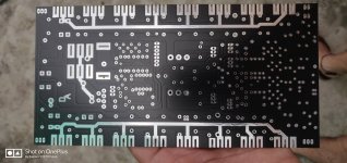
I'm posting this one because it's the only one so far that has been actually made by a board house, so the gerbers have been used and accepted by them.
Plus someone is working on building a few right now, and he's even sent me a few bare boards, which look super nice.
I didn't rewrite Jens' excellent build document, with the bunch of maths and all that, because although there were many tweaks and some changes made on this variant compared to his, it's still worth using his build info as a guide, because it still mostly applies.
Now as I mentioned, I also did some cad along with this, and I can post some more visuals next. This may be of interest to some amp builders who are mostly at a dead end wanting to build a leach designed by Jens but don't have original MCAD files to do more work on it and put out updated gerbers.
What version of Jens' Leach Clone did you base this from? Sorry did not find that information anywhere. The two versions I know of is 5.6.10 and 7.4.6 as per the schematic footer.


Would be this amp suitable to power a peerless 830500 subwoofer? Anybody use it in that way? Or maybe advice for another amp.
What version of Jens' Leach Clone did you base this from? Sorry did not find that information anywhere. The two versions I know of is 5.6.10 and 7.4.6 as per the schematic footer.
Well, it's kind of an amalgam of several versions from Jens' designs, with added tweaks and adjustments that were discussed but not yet implemented by Jens at the time.
Some things never made it into a new design, since Jens pretty much disappeared from the forums. But I picked up from there and applied a lot of tweaks.
One thing that was implemented at some point was adding resistors to the VI limiter to make it more of a true "VI", as the simpler one from Leach isn't quite there.
One goal was to get the bias spreader temperature sensing devices much closer to the power devices, because they were quite far physically in Jens' designs, which adds additional lag time.
I figured the closest they could get are right on top of a power device. We'll see how that goes, as the plastic casing isn't that great at thermal transfer, but at least they are physically as close as they can get. Plus I split them into 2 groups, sensing a power device from both sides (rails).
I further tweaked more things in a subsequent version, with some layout adjustment to allow for larger parts in some places.
One thing that really doesn't belong there are the fuses. Those introduce more losses and series resistance into the rails, plus potential for bad contacts in the long run. Something much better needs to be used, like SSRs on both rails, plus SSR on the amp's output.
Many thanks ThereseHello, have you an Circuit for this - SSRs on both rails, plus SSR on the amp's output.
What supply rail voltage does this BOM correspond to? If it is the same as Jens' design (+- 68 V), then the voltage rating of C1 and C14 is a bit optimistic.I made a refreshed BOM lately that accounts for the changes in some values from the BOM from Jens.
I figured I'd upload it here for reference.
I hope I didn't make any mistakes. It seems ok.

- Home
- Group Buys
- Jens Rasmussen Leach clone group buy