It is exactly that. I deliberately setup a second order filter, with enough Q to keep 'er ringing for several seconds. The intent was a triggered tremolo. If you can "ride the swells" with your rhythm (you have to keep time to something, unless you're a John Cage) you can "pump it along" to be a continuous effect.like the pulse response of a resonant circuit with a certain Q-factor.
With the particular implementation I chose, the cost is a slow, slow attack on the compression part. I'm thinking out a solution for that and have dispensed with the wavy-gravy effect for now. Back to a decent straight compression effect, on the signal going into the output tubes, via a straight up op-amp full wave rectifier. I want to get that part tight, then add in the wave as a control signal "mix" to the Vactrol VCA.
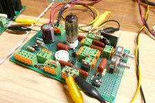
Hey, not so bad - just needed to successfully get that board in half. Down the groove where the DIP ICs sit across, right? I bet with a reciprocating blade and a nice score down that sticky back stuff you could get it cut clean.My brilliant idea was to rip one in half lengthwise along the existing groove, so I could put a pair of tube sockets in the middle and mount all of it to a small piece of PC board stock.
Oh yeah. This amp has some small cathode balance pot soldered to the chassis. Obviously the resistance on either side of the wiper is something; when I saw the AC drive clamped to the bias voltage tube go to zero current when its partner was handling a large AC signal, I knew that corresponded to the ring I was hearing from the OPT. I lost my current balance in the OPT; at idle, the V drops across the pot matched reasonable well.Eventually I made quite a few "Turbo Champs" and no two were the same. They did sound nice cranked, so maybe the use of a "real" SE OPT helped.
I suppose if I really wanted a challenge, I could simultaneously turn the AC clamped tube on harder DC wise, to try to keep a current balance in the OPT primary. I have a control signal to leverage. A lot of work to tune that up, maybe sounds like .... anyway. I think I'll stick with trying to get a pleasant sounding, musically useful compression effect going on.
Yes, I wound up clamping a jig saw in my old Black and Decker Workmate with its blade pointing up and zipping right through a second better quality Amazon sourced board. The fine tooth blade didn't even mess up the sticky stuff. The whole idea wound up in the trash anyway, which led me to the design I have now. it's more old school breadboard style with easily replaceable parts. The two tube sockets are wired in parallel so I can test 7 pin and 9 pin tubes in it.Down the groove where the DIP ICs sit across, right?
Member Windcrest77 found these neat little spring loaded connectors for quick changes of small parts, or even minor circuit rewiring. Info is in post #77 of this thread:
https://www.diyaudio.com/community/...obby-the-way-i-always-wanted-to-do-it.410333/