#8,370 Is there a difference in the value of R9\R13 (2k2\k300)? (R7,8\R11,12)Here is the operation of the two versions when the load resistance changes.
https://patents.google.com/patent/US3246251#8,370 Is there a difference in the value of R9\R13 (2k2\k300)? (R7,8\R11,12)
overall feedback: "Real amps do play."
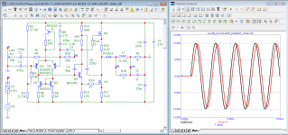
A real amplifier has well-defined parameters. Therefore, it is not just a set of iron that plays (you can build both a barn and a palace from the same bricks), but a device with certain properties. The amplifier has a lot of these properties. Until recently, no attention was paid to the signal transit time (time Propagation Delay), and it is precisely this that determines the sound quality. In the inverting version, the delay time (GDT) has not increased. Therefore, it is hoped that, taking into account the improvement of other parameters, this version will sound better than the original.
At the heart of the JLH-69 amplifier is a unique output stage, characteristic only for this amplifier, with its inherent advantages and disadvantages and capable of operating only in class A. As you can see, the output stage remained unchanged. The quiescent current is adjusted in the same way as in the original circuit.
OldDIY: "Is there a difference in the value of R9\R13 (2k2\k300)? (R7.8\R11.12)"
Replaced the resistors so they don't confuse you. As you can see the parameters have not changed. As for the resistor R13, the lower this resistance, the faster the transistor Q7 turns off. Active control of transistor Q5 using a current mirror made it possible to expand the total power bandwidth and reduce the introduced distortions while maintaining the signal propagation delay time responsible for high-speed distortions.
OldDIY, thanks for the patent link
Attachments

Last edited:
I would really like someone from the group to assemble this amp in reality (ideally someone who has a jlh version 69) and say what they think about it and if someone else offers to make and sell the pcbs, I will buy just to be sure not to miss a wonderful amp.
Can work in class AB with output transistors Darlington, Shiklai or Mosfet. DIY kits (Ali) and professional amplifiers available (Alto, NE5532) 🙂JLH-69 amplifier is a unique output stage, characteristic only for this amplifier, with its inherent advantages and disadvantages and capable of operating only in class A
Attachments

Last edited:


in my opinion, a successful replacement of the output transistors with field ones. Quiescent current is 3 times lower, does not require output inductance. Good for highly sensitive acoustics with an impedance of 15 ohms.Chinese version (class AB)
Attachments


Those with heatsinks that do not allow 40 watts per channel to be dissipated in idle mode can replace the output bipolar transistors with field-effect transistors. In this case, the dissipated power will decrease by 3 times.
Attachments

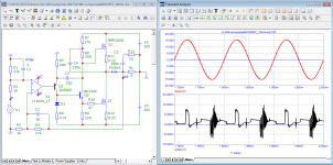
It is known that class AB is characterized by crossover (switching) distortions that occur when the signal passes through zero. To measure such distortions, a two-tone signal of 100 Hz and 20 kHz in a ratio of 3:2 was used. Distortion products are measured using a specially designed notch filter. The test showed that there is no hint of switching distortion opposite the signal transitions through zero.
Attachments


Petr_2009,
It appears to me that you are still trying to propagate the theory of First Cycle Distortion by 'polluting' threads that discuss other subjects (such as Bob Cordell's book on Power Amplifiers) and where the end results of your off-topic comments led to significant frustration of other members.
As the title suggests, this thread is for discussion about JLH's 10 watt Class A amplifier. The amplifiers that you have described seem to bear no resemblance to JLH's amplifier in design, performance etc. and I would like to suggest that you start another thread about your thoughts of derivatives amplifiers such as was done with the " Musings on amp design... a thread split" thread.
Another good example of this being done was the FET version of the JLH.
I hope the forum moderators will agree with this.
Kind regards
Last edited:
This forum is popular all over the world and visitors who do not speak English inevitably have to translate information into their own language. Therefore, I did not translate the text of the test description into English. I should note that I analyzed a large number of various modifications of the JLH-69 amplifier. The vast majority of them are not worth attention and it was a pity to spend time on their research.
Why amplifier modifications are related to the JLH-69, I hope it is clear from the material at the very beginning.
I will be glad if this material is useful to someone.
Best regards
Alexander Petrov
Why amplifier modifications are related to the JLH-69, I hope it is clear from the material at the very beginning.
I will be glad if this material is useful to someone.
Best regards
Alexander Petrov
Attachments
I wonder if anybody ever built JLH amp with op-amp front-end?
This seems to be working (simulating) ok.
Sim attached.

This seems to be working (simulating) ok.
Sim attached.
Attachments
Last edited:


The theory says: loop gain = linearity
Here are a couple of tests
I'm not sure that it will work stably with speaker cables with low inductance.
Here are a couple of tests
I'm not sure that it will work stably with speaker cables with low inductance.
Attachments


Last edited:
Petr_2009,
It appears to me that you are still trying to propagate the theory of First Cycle Distortion...
The amplifiers that you have described seem to bear no resemblance to JLH's amplifier in design,
Which post or line of the JLH-69 Review of Possible Improvements talks about the distortions of the first period (FCD)?
One version of the JLH-69 update is presented as JLH-2003 (JLH-2005).
https://sound-au.com/tcaas/jlhupdate.htm
Let's try to figure out whether it is worth going down this path of the update.
A few comparison tests against the original are presented here:
http://forum.vegalab.ru/showthread.php?t=11445&p=3043830&viewfull=1#post3043830
https://sound-au.com/tcaas/jlhupdate.htm
Let's try to figure out whether it is worth going down this path of the update.
A few comparison tests against the original are presented here:
http://forum.vegalab.ru/showthread.php?t=11445&p=3043830&viewfull=1#post3043830
I have a good dozen things in the shed (from .75w to 200W), including the Altronics 20W class A amp which looks surprisingly close to your proposal.Let's not guess on coffee grounds. Give a diagram of what you have in the shed.
The original '69 JLH (with regulated supply) is what stays in the system.
To save you reading the whole 420 pages of this thread, there are a few likely candidates as to why:
1. No differential pair. The differential pair cannot benefit from loop gain & feedback. Indeed, the more feedback, the more the diff pair gets "kicked around" the nominal operating point. It's also likely to pump out heaps of 3rd, 5th and 7th. Yet everyone builds the diff amp from bipolar transistors - the worst possible choice. (See everyone from Crowhurst to Olsen)
2. Low loop gain: so clipping (which is inevitable) will not upset all the bias points in the amp. This is very audible & very measurable. All the "all amps sound the same" tests require no clipping. Hamm '73 outlines why, even without bias point drift. Even Putzeys accepts this.
3. Not hiding non-linearities behind heaps of feedback. See Hugh Dean's (AKSA) work for why, but again it's nothing that Crowhurst didn't say.
4. All of the above mean that the amplifier remains mostly in control through out the upper frequencies. Not like my old Tillbrook ETI 5000
Now, that doesn't mean that there's no room in the world for an "improved" JLH. But chasing lower THD by turning it into an op-amp is not the way to go.
"The total harmonic distortion is not a measure of the degree of distastefulness to the listener and it is recommended that its use should be discontinued."
D. Masa, 1938
- Home
- Amplifiers
- Solid State
- JLH 10 Watt class A amplifier