MJF solved and drew it for you 😀...
Whoa... I didn't realize that... 😕
MJF, so sorry for that and many thanks for taking the time to simulate this! 😱
I thought the schematic was some example you took from the web. Silly me.
I noticed that you used the RC 488D as reference.
I'm using the JRC NJM4558D.
I guess your test schematic applies all the same (the resistor and capacitor values) since both op amps are practically clones?
Much appreciated.
JMFahey, many thanks for pointing out this for me.
I was completely out of focus about MJF post.
Last edited:
........
I noticed that you used the RC 488D as reference.
I'm using the JRC NJM4558D.
I guess your test schematic applies all the same (the resistor and capacitor values) since both op amps are practically clones?
............
hello,
...........i used a RC4558D in the schematic.......
Hi all,
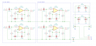
I reached the final design for this project.
I leave it here for anyone that may wish to do this guitar preamp BOX (for 4 guitars).
The main idea of this project was to raise the guitar signal from "Instrument level" to "Line level".
Many thanks to all of you that commented and suggested on how to change this project for better.
My special thanks and gratitude to MJF and JMFahey.
I decided to replace all POTs with fixed values resistors (R3, R4, R15 and R16) like suggested by MFJ and JMFahey, yet, if someone would prefer to use "volume" pots, then replace these resistors by POTs.
NOTE: I decided to go for a dual layer PCB.
In the front side of the PCB I decided to put only the +12v; -12V; tracks (in red).
The rest of the circuit will be printed in the PCB back side (in green).
@craigtone
I understand your worries, yet the Power Supply Regulator Circuit is already well filtered, (see the PWSR schematic), unless you see any other reason to use those capacitors, that I'm missing.
If anyone else notices any problem or issues with this circuit, please mind to comment on it.
Many thanks.
Attachments


Last edited:
- Status
- Not open for further replies.