I purchased an amp on ebay that at first I didn't recognize but I believe it is some sort of Knight KM-15. I want to turn it into a guitar amp. Here are the photo's from the auction.
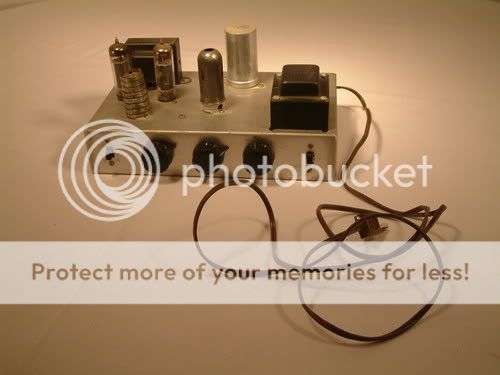
As you can see, other than the knobs, chassis, and location of one of the 12XA7's, it looks very close to the Knight.
I have practically no experience with tube electronics but want to give this a whirl. I've purchased the rectifier tube for the amp and I should have it about the time the amp arrives.
My 1st question is whether or not it is OK to remove all the tubes but the rectifier and power it up to check voltages to verify that the rectifier/transformer is working.
My plan of attack was this:
1 - confirm voltage from transformer
2 - replace cord with grounded cord
3 - test amp - to see if it works (with an mp3 player in the tuner jack)
4 - rebuild the phono pre-amp circuit for guitar
Any suggestions? Thoughts? Is this a "real" Knight or just a home-made look alike? The wiring sure looks like the Knights I've seen.
I'll post better photo's once I get it.
Thank in advance,
Rick
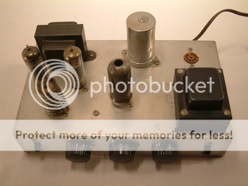
Well, I got the amp and I'm quite pleased with what I got. Here are the closeups I promised.
The amp is clean as you can see. I think it's a well built clone. When it was built... I don't know?
I was curious if it worked or not and popped in a rectifier tube and it does work. Does it work like it should?? I don't know.
Does anyone know of a way to find out about the transformers? I took closeups of thier numbers in case the meant anything. I couldn't find anything on the web. I don't have a parts list for an actual knight to know if they are thier numbers or not.
This is my second project amp (first timer) I listed the other under a topic (Mystery Amp). This seems much newer and definitely more mod friendly than the other. I think this will be the one I move forward with.
Any suggestions? my goal is to take the phono preamp and convert it for guitar. Hopefully I'll be able to leave the power amp portion alone.
Rick
An externally hosted image should be here but it was not working when we last tested it.
An externally hosted image should be here but it was not working when we last tested it.
An externally hosted image should be here but it was not working when we last tested it.
An externally hosted image should be here but it was not working when we last tested it.
An externally hosted image should be here but it was not working when we last tested it.
An externally hosted image should be here but it was not working when we last tested it.
An externally hosted image should be here but it was not working when we last tested it.
An externally hosted image should be here but it was not working when we last tested it.
An externally hosted image should be here but it was not working when we last tested it.
An externally hosted image should be here but it was not working when we last tested it.
An externally hosted image should be here but it was not working when we last tested it.
An externally hosted image should be here but it was not working when we last tested it.
The amp is clean as you can see. I think it's a well built clone. When it was built... I don't know?
I was curious if it worked or not and popped in a rectifier tube and it does work. Does it work like it should?? I don't know.
Does anyone know of a way to find out about the transformers? I took closeups of thier numbers in case the meant anything. I couldn't find anything on the web. I don't have a parts list for an actual knight to know if they are thier numbers or not.
This is my second project amp (first timer) I listed the other under a topic (Mystery Amp). This seems much newer and definitely more mod friendly than the other. I think this will be the one I move forward with.
Any suggestions? my goal is to take the phono preamp and convert it for guitar. Hopefully I'll be able to leave the power amp portion alone.
Rick
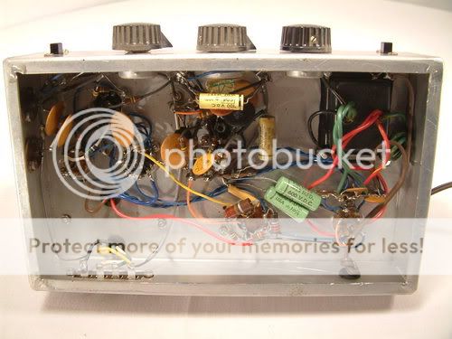
I don't feel like taking the covers off mine right now, but those DO look like the Knight transformers. Even some of the caps look the same.
Sounds like a decent plan, but a lot of the amp's character is in the preamp. You might consider mounting this in a cabinet with a single rack space at the top for mounting a guitar preamp which you might be ablet to swap out. At least that's what I'd do, so I could use it immediately and see whether I want to build my own preamp later.
I've thought the same thing about the transformers and componenets looking like a true knight. Maybe whoever had this damaged thier chassis and made their own??
As for the pre-amp, it has two 12ax7's one is the pre-amp for the phono imput. The tuner input bypasses that and goes directly to the 2nd 12ax7. I figured I'd leave that part and the push/pull section alone and modify the phono pre-amp to be a guitar pre-amp.
Sound feasable??
As for the pre-amp, it has two 12ax7's one is the pre-amp for the phono imput. The tuner input bypasses that and goes directly to the 2nd 12ax7. I figured I'd leave that part and the push/pull section alone and modify the phono pre-amp to be a guitar pre-amp.
Sound feasable??
Well, I've added a grounded cord and fuse. I removed the 18K resistor from the phono input that went to ground and replaced it with a 1M resistor. I removed the .1uf capacitor from the phono inpu to the grid on the 12AX7 pre-amp and replaced it with a 68K resistor. I connected an 8Ohm speaker I had lying around (Not a guitar speaker... just a full range one) turned the volume control all the way down, plugged the amp in and flipped the power switch. Tubes all lit. I gave it a bit to warm up and slowly turned up the volume. There was next to no hum even at full volume. I figured for giggles, I'd plug in a guitar and see what it does. To my surprise, it rang out pretty loud. I played around with it a while adjusting the bass and treble controls, playing between the guitar volume control and that of the amp. It is definitely working.
The only issue I have is the sound quality. It's too clean and bright. It sounds like I'm plugging the guitar into a home stereo... I'm guessing that is because the amp was originally designed for home audio use not a guitar amp. I plan to rebuild the pre-amp/tone control section to more match that of a guitar amplifier. I've looked at several schematics and think I have a plan.
Now for the questions for you guru's. Looking at the km-15 schematic, it shows 150V coming from the power supply being dropped to 75 at the pre-amp stage through 150K resistors to the plates of the 12AX7. Most guitar amps I see have this voltage much higher... in the 200 to 300V range. Is this something I should adjust?

I circled the resistor in question. If I wanted to raise the 150V coming out here to something like 225 for example. Would I just calculate the current by dividing the voltage drop by the resistance... (330-150)=180 /82000 = .0022A then divide my new voltage drop by that to get my new resistance value? (330-225)=105 / .0022 = 47,833 Ohms (47K).
Is this the correct way to be thinking?
Another thing I've noticed. Most guitar amp schematics I find have the tone stack between the 1st and 2nd pre-amp stage. This one places it after and it seems to be fed from the output transformer's output. If I were to move the tone stack what would I do with the feedback line. Remove it alltogether? Tie it back in only w/o the tone stack where it is?
So many thoughts running through my brain 😀 ... This is fun
Rick
The only issue I have is the sound quality. It's too clean and bright. It sounds like I'm plugging the guitar into a home stereo... I'm guessing that is because the amp was originally designed for home audio use not a guitar amp. I plan to rebuild the pre-amp/tone control section to more match that of a guitar amplifier. I've looked at several schematics and think I have a plan.
Now for the questions for you guru's. Looking at the km-15 schematic, it shows 150V coming from the power supply being dropped to 75 at the pre-amp stage through 150K resistors to the plates of the 12AX7. Most guitar amps I see have this voltage much higher... in the 200 to 300V range. Is this something I should adjust?
I circled the resistor in question. If I wanted to raise the 150V coming out here to something like 225 for example. Would I just calculate the current by dividing the voltage drop by the resistance... (330-150)=180 /82000 = .0022A then divide my new voltage drop by that to get my new resistance value? (330-225)=105 / .0022 = 47,833 Ohms (47K).
Is this the correct way to be thinking?
Another thing I've noticed. Most guitar amp schematics I find have the tone stack between the 1st and 2nd pre-amp stage. This one places it after and it seems to be fed from the output transformer's output. If I were to move the tone stack what would I do with the feedback line. Remove it alltogether? Tie it back in only w/o the tone stack where it is?
So many thoughts running through my brain 😀 ... This is fun
Rick
Not a good idea. Assuming this is an RIAA preamp stage for MM cartridge, it needs 47K input. The original 18k may have been an attempt to use the 'wrong' resistance to correct some inadequacy in the preamp stage.I removed the 18K resistor from the phono input that went to ground and replaced it with a 1M resistor. I removed the .1uf capacitor from the phono inpu to the grid on the 12AX7 pre-amp and replaced it with a 68K resistor.
An even bigger mistake is replacing the coupling cap with a resistor. You have just ruined the input stage bias! This stage uses grid current bias via the 3M3 resistor, which you have now arranged to be shorted out when a cartridge is plugged in.
The low supply voltage to this stage is probably because of the grid bias arrangements. You can't simply raise the voltage; you would need to redesign the stage.
Unless you know what you are doing you should leave the circuit unchanged.
I thought the replacement of the cap would possibly change the bias of the 1st stage after I looked at it more. I am however never going to use this as a phono input. So the RIAA circuitry is not an issue since I plan to entirely rebuild the preamp stage per the print of a known good guitar amp schematic.
I plan to remove both the "tuner" input and the "phono" input and replace the phono with a 1/4" jack for guitar input. Essentially, in what I did above, I was just wanting to see if it would amplify and work, which it does. I now plan to rebuild the pre-amp like you might find in a fender bronco or champ amp. This should correct any screw up with the bias since the entire section will be re-wired.
Any thoughts on the feedback wire?
It uses feedback as part of an active tone control. Unusual circuit, I would have thought stability would be a problem.
The phase splitter is strange too - an STP (Short Tail Pair). It will have appalling balance, so even-order cancellation in the output stage will be poor. Might be OK for guitar use.
This whole circuit appears to have been built down to a price.
The phase splitter is strange too - an STP (Short Tail Pair). It will have appalling balance, so even-order cancellation in the output stage will be poor. Might be OK for guitar use.
This whole circuit appears to have been built down to a price.
The splitter is a floating paraphase and should achieve reasonably good balance, probably not the ideal for a guitar amplifier, but not too bad. These tend to become a bit unbalanced at high frequencies.
I would replace the phono stage with a conventional guitar amp input stage and make sure that you have conventional RC based cathode bias on the first stage.
Some of the sound of a guitar amplifier is in the output transformer so you might consider replacing the existing transformer with one intended for guitar amp use.
 Since this is being used as a guitar amp. I will retitle and move to I&A where it belongs.
I would replace the phono stage with a conventional guitar amp input stage and make sure that you have conventional RC based cathode bias on the first stage.
Some of the sound of a guitar amplifier is in the output transformer so you might consider replacing the existing transformer with one intended for guitar amp use.
Since this is being used as a guitar amp. I will retitle and move to I&A where it belongs.It uses feedback as part of an active tone control. Unusual circuit, I would have thought stability would be a problem.
The phase splitter is strange too - an STP (Short Tail Pair). It will have appalling balance, so even-order cancellation in the output stage will be poor. Might be OK for guitar use.
This whole circuit appears to have been built down to a price.
The phase splitter is a floating paraphase type.
These were intended as very inexpensive not quite hifi amplifiers. (Still better than found in a lot of consoles.) Definitely built to a price.
Yes, you are right. I didn't spot the feedback to the second grid. Ignore my comments on the PS in post 9.kevinkr said:The splitter is a floating paraphase
One other comment I would make belatedly since you plugged it in without checking or reforming capacitors is that this is a really BAD plan. What you should have done is carefully checked the capacitors and gradually brought the amplifier up using a ballast lamp and variac. You got very lucky that the electrolytic supply capacitor - which should be replaced did not short, explode or otherwise misbehave. Plan on replacing it soon along with all of the paper coupling and bypass caps! Antique Electronic Supply sells replacement FP types.
- Status
- Not open for further replies.
- Home
- Live Sound
- Instruments and Amps
- Knight KM-15 As Guitar Amp??