hello,
I like to know if there is any "hidden" disadvantage on use a ladder stepped attenuator vs a series stepped att. I mean, it is an obvious thing that on ladder type there is only 2 resistors + 2 contacts through the signal path on each channel and on the series there are 42 (evaluating to get a 41 steps att.) resistors + 1 contact on each channel across the signal path. Both types preserve the impedance.
The Ladder use 1% metal resistors and silver contacts, series use non-inductive SMD resistors and silver contacts.
From the sound point of view, one might think that the ladder type, due to have less components on the signal path sounds more pure, but have the double of all mechanical parts and a good rule almost always is "keep it simple". On the other hand, if the SMD resistors are transparent enough maybe there is not that big sonic difference. I am only guessing as I have never used one of this. So I will appreciate a lot any comments from those who have had experience with both types.
The cost is no object for one of this two options, knowing that there is a disproportion on cost/benefit because the ladder use the double of everything for little advantage in sound. No matter, but if there is reliability problems on the medium term because of a bigger probability of failure due to more parts involved; in that case, I will prefer the other.
Please don't offer me other possibilities; I would like to evaluate only this two.
Best regards
p.s. I already check golpoint web paga and the reason why they stopped to build the ladder attenuator and also this one http://diyaudio.co.kr/wwwboard1/data/board1/compare.pdf that claim thar are the best
The series device uses less components in total for a given number of steps.
For most people, 42 steps are never needed as we have a set of five or six preferred listening levels, and another five or six that we use for other situations (background music, tearing it up, and some very quiet/very loud recordings).
A 23-step device is usually sufficient and maybe even 12, if you can work out exactly what you need (this would mean long term listening with a process of noting down the attenuation ratios you use). When you whittle this down to such few steps, a series attenuator can be designed for uncompromising performance. Nude foils etc. And then, you can have a two-stage series attenuator with a coarse and fine control for better precision if you can afford it. Maybe the good ladder type will then cost similar to this.
I know you asked only for a comparison between these two types, but a relay type attenuator may be designed for a massive number of steps using a small number of resistors. If you use good relays, it is as sonically transparent as a good switch and the resistors here can be extreme quality as well.
Of course, that is if you believe that resistors have a contribution to the sound. I personally prefer the ladder type where I need one (of my dozen or so amps only one has a passive volume control).
well, yes, that is my point, but all the resistors are in the signal path. So, depends on how transparent (expensive) are those resistors.The series device uses less components in total for a given number of steps.
I began this search because I will build a pair of high efficiency speakers and want a better control, more transparent, than my TKD 2511 2CP pot that, moreover, started to fail after 10 years of service. More steps is more like a continuous attenuation, like a potentiometer. Most of the attenuators with less steps, don't have the ability to select a good level when you hear at low level with high eff speakers/hi gain amp.For most people, 42 steps are never needed as we have a set of five or six preferred listening levels, and another five or six that we use for other situations (background music, tearing it up, and some very quiet/very loud recordings).
A 23-step device is usually sufficient and maybe even 12, if you can work out exactly what you need (this would mean long term listening with a process of noting down the attenuation ratios you use). When you whittle this down to such few steps, a series attenuator can be designed for uncompromising performance. Nude foils etc. And then, you can have a two-stage series attenuator with a coarse and fine control for better precision if you can afford it. Maybe the good ladder type will then cost similar to this.
I am agree with you that I can customize the attenuation ratio with less steps, to match my more common levels of hearing, but is like to put a cage on the possibilities. I have one or two typical level to hear music when I'm alone, but some times this change absolutely...that's depends on my mood or if I'm alone hearing or with people or if Im on the room next to my audio room, etc.
But is a good idea to make a personal stepped attenuator... but this will be my first stepped so I prefer to have one ready to use as also need to replace urgent the pot.. then maybe I will, of course, build a custom one.
Well, yes, conceptually, less resistors in the signal path produce more peace of mind, although the improvement in transparence were barely audible.Of course, that is if you believe that resistors have a contribution to the sound. I personally prefer the ladder type where I need one (of my dozen or so amps only one has a passive volume control).
My concerns are on the reliability of using a device with more components, more moving parts and, eventually, with some noises when you turn the knob. This last issue, as far as I know is not always present. I will take a look to your proposition by the way and thanks so much for your contribution
Regards
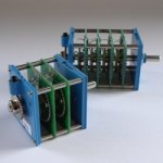
p.s. The series and the ladder that I'm evaluating are the 41 steps by Acoustic Dimension from Holland. Only good reviews
Attachments
There is a rather large assumption there.beto1 said:So, depends on how transparent (expensive) are those resistors.
Does it? Only for those who believe the naive view that more components equals more distortion. One of the main distortion mechanisms in resistors is temperature coefficient (although even this is extremely small and can often be ignored) so to get less distortion you need to spread the signal voltage over more resistors. In one thread I saw someone suggest deliberately using 10 resistors in series instead of 1 (for NFB) for this very reason.Well, yes, conceptually, less resistors in the signal path produce more peace of mind
The weak point in any variable voltage divider is the contact(s), so avoid putting the signal through contacts if possible.
Interesting!. But less distortion when are working in parallel or in series?Does it? Only for those who believe the naive view that more components equals more distortion. One of the main distortion mechanisms in resistors is temperature coefficient (although even this is extremely small and can often be ignored) so to get less distortion you need to spread the signal voltage over more resistors. In one thread I saw someone suggest deliberately using 10 resistors in series instead of 1 (for NFB) for this very reason.
Also depends on resistors value? When the source output voltage is high, I guess.
So, to land on my question, the problem here don't be the amount of resistors but the amount of contacts. The series att has only one (with SMD resitors) and the ladder has two (with metal film resistors).The weak point in any variable voltage divider is the contact(s), so avoid putting the signal through contacts if possible.
Regarding this point one difference with other attenuators, according to the web site description:
[FONT=Arial, Helvetica, sans-serif]"Not commonly known, but in available attenuators the switching action in fact consists of two separate pressure contacts. A pressure contact from outer ring (input) to the whipper and from whipper to the inner ring (output).
[/FONT][FONT=Arial, Helvetica, sans-serif]After the example of high current rheostats, we have replaced the pressure contact from whipper to output with a fixed flexible wire. This is a labor extensive solution, but results in a much more open, transparent and stable attenuator. "[/FONT]
Last edited:
Forget the angst and neuroses and just get the Acoustic Dimension attenuators. They are a very nice attenuator.
se
se
Steve,Forget the angst and neuroses and just get the Acoustic Dimension attenuators. They are a very nice attenuator.
se
that is out of question, but if you read the thread, is about which one, series or ladder (and why).
Neither are good for audio purpose, as they involve contacts
You should broaden your horizon and research LDR's IMO the best
followed by digital potentiometers .
Cheers / Chris
You should broaden your horizon and research LDR's IMO the best
followed by digital potentiometers .
Cheers / Chris
are you a kid?*sigh*
Neurotics.
se
If you are unable to contribute to the subject, it is wiser to remain silent.
Hello Chris, thans for your answer.
regards
This is almost new to me. I will take a look to LDR's.LDR's IMO the best
followed by digital potentiometers .
Cheers / Chris
regards
I belive what GoldPoint meant at some point going from ladder type to series ones with SMD soldered directly on the PCB of the switch was that the series one's signal path lenght was shorter than the ladder type with two resistors soldered to PCB. They also confiremd it as they claimed by listening (this what I remember reading about this few years ago so correct me if I'm wrong at some point).
It is all fine but what scares me in this SMD version regardles of SMD resistor quality is the number soldering points and PCB points used.
I have played a lot in the past with attenuators. My conclusion in general was the less components in signal path the better (also to ground). The best results I achived soldering two resistors (for given loudness) dierctly to signal wires at RCA's. So I think the great role plays the switch with it's contacts and quality. I'm positive single resistor will be lot better than 12 or 24 of same value soldered directly one to another mostly becouse of soldering connections. I also doubt any SMD even single will be better than some expensive Vishay, though GoldPoint claim the opposit, but they make living out of it so they are not objective. If any SMD would be better some of the butique producers would switch to this solution, I haven't heard of any.
It is hard topic and I belive good pot will be better than poor or average switch no matter ladder or series.
I personally never got satysfying results with any switch. One of the best was I think simple vintage 12 steps one which I wired in series, but mostly becouse at the volume point I used to listen to maximum of 3 resistors were in series. I also used few Elmas and even though make before brake they used to make some clicks and pops in ladder type configuration. As far as I recall Shallco are considered one of the very best but never tried one. Also getting the right velue of resistors for ladder type is very hard out of ready available vaues.
My 5 cents
Last edited:
are you a kid?
If you are unable to contribute to the subject, it is wiser to remain silent.
No. I've been involved in the industry for some 30 years. But as I've grown older, I've also become more weary of the neurosis that has pervaded this industry more and more over that 30 years.
Bottom line, the series attenuator will be just as audibly transparent as the ladder. So worrying about the resistors in the signal path, other than from a purely philosophical standpoint is just being neurotic.
se
The only thing that can go wrong with the ladder attenuator, which electrically seems just like a stepped potentiometer as you describe it, is a non-uniform frequency response due to improper wiring and shielding, and unintended capacitive coupling within the circuit.
Basically, if the output node of the switch is allowed to have too much capacitive coupling to the input, or to a higher voltage node on the attenuator, there will be a constant capacitive coupling from input to output, which will cause the HF response to rise as attenuation increases - the capacitive coupling will remain constant but the attenuated signal becomes smaller. Sum the two, and the attenuated signal becomes proportionally brighter as the direct signal is attenuated.
This is similar to the ridiculous case where a fader is wired to a console channel PCB with a piece of shielded twisted pair, one wire for the top of the track, one for the wiper, and the shield for the bottom of the track. Yeah, this sounds stupid, but I've seen too many otherwise good consoles do this. The 'top of track' lead couples to the 'wiper' lead and you get HF feedthrough.
While that's a dramatic case, it's still possible to wire things up wrong, and to fail to properly shield or ground the send and return signals inside of the attenuator. However, get that right, and a switched ladder is hard to fault.
Use quality metal film resistors, make sure the contacts are clean and lubricated, wire it up properly, and it should work really well.
You mean a fixed volume level? Well, on the conceptual point of view, of course will be fine, but most people need more adjustability for different situations. You are not the only one that advise me this solution. Maybe doing huge act of abstraction, I can determine at least 5 or 6 typical levels. Of course, leaving outside of the list some less common.I have played a lot in the past with attenuators. My conclusion in general was the less components in signal path the better (also to ground). The best results I achived soldering two resistors (for given loudness) dierctly to signal wires at RCA's. So I think the great role plays the switch with it's contacts and quality. I'm positive single resistor will be lot better than 12 or 24 of same value soldered directly one to another mostly becouse of soldering connections.
Well thank you for share your experience. Maybe less steps with the attenuation ratio that I need to not be too loud at the firsts steps with a combination of high gain amp/hi sensitivity speakers could be a good idea.It is hard topic and I belive good pot will be better than poor or average switch no matter ladder or series.
I personally never got satysfying results with any switch. One of the best was I think simple vintage 12 steps one which I wired in series, but mostly becouse at the volume point I used to listen to maximum of 3 resistors were in series. I also used few Elmas and even though make before brake they used to make some clicks and pops in ladder type configuration. As far as I recall Shallco are considered one of the very best but never tried one. Also getting the right velue of resistors for ladder type is very hard out of ready available vaues.
My 5 cents
The goal here is exactly what you are pointing: which one can offer the more short/transparent path. The quality of the contacts are essential also.
Regards
Thanks Monte, you have a good point here. I will check with Peter from AD regarding this. But I believe that there is no problem.The only thing that can go wrong with the ladder attenuator, which electrically seems just like a stepped potentiometer as you describe it, is a non-uniform frequency response due to improper wiring and shielding, and unintended capacitive coupling within the circuit.
While that's a dramatic case, it's still possible to wire things up wrong, and to fail to properly shield or ground the send and return signals inside of the attenuator. However, get that right, and a switched ladder is hard to fault.
Use quality metal film resistors, make sure the contacts are clean and lubricated, wire it up properly, and it should work really well.
Regards
Someone who is worried about resistor distortion would not use LDRs as they are significantly less linear than a normal resistor. However, LDRs might suit someone worried by contact distortion.Chris Daly said:You should broaden your horizon and research LDR's IMO the best
followed by digital potentiometers .
The only thing that can go wrong with the ladder attenuator, which electrically seems just like a stepped potentiometer as you describe it, is a non-uniform frequency response due to improper wiring and shielding, and unintended capacitive coupling within the circuit.
Basically, if the output node of the switch is allowed to have too much capacitive coupling to the input, or to a higher voltage node on the attenuator, there will be a constant capacitive coupling from input to output, which will cause the HF response to rise as attenuation increases - the capacitive coupling will remain constant but the attenuated signal becomes smaller. Sum the two, and the attenuated signal becomes proportionally brighter as the direct signal is attenuated.
This is similar to the ridiculous case where a fader is wired to a console channel PCB with a piece of shielded twisted pair, one wire for the top of the track, one for the wiper, and the shield for the bottom of the track. Yeah, this sounds stupid, but I've seen too many otherwise good consoles do this. The 'top of track' lead couples to the 'wiper' lead and you get HF feedthrough.
Why is that ridiculous?
How is a few pF of capacitance between the input and output leads going to have any effect anywhere near the audible range?
se
If you had taken the time to read the thread, you'd realize that this was not the only point. Probably it is more neurotic and unwise the rush to qualify opinions rather than contribute with the personal knowledge and certainly less effective to transmit an idea. Anyway, thanks for share your technical experience. I am agree about that the industry molds the opinion of people to sell products, btw.No. I've been involved in the industry for some 30 years. But as I've grown older, I've also become more weary of the neurosis that has pervaded this industry more and more over that 30 years.
Bottom line, the series attenuator will be just as audibly transparent as the ladder. So worrying about the resistors in the signal path, other than from a purely philosophical standpoint is just being neurotic.
se
Last edited:
- Status
- Not open for further replies.
- Home
- Source & Line
- Analog Line Level
- Ladder stepped attenuator downsides please