Very nice find. Current limiting resistor and the protection diode both built in. 6V version exists. Stainless steel bezel and as a bonus it looks old school/good too. Just the two wires to the heater windings so safe as almost nothing can be done wrong and most easy to use.
Seems a winner!
Seems a winner!
Last edited:
White is negative. Cap is 5uf. No flicker at all.So the neg stripe on the cap is on the white wire right? What is best like a 220uf?
For direct mains connection (230V AC), this little PCB does the job.
Conrad Components LED electronic ballast PCB 230 V AC 2 mA | Conrad.com
Conrad Components LED electronic ballast PCB 230 V AC 2 mA | Conrad.com
For direct 230 Vac supply I've always used a capacitor to drop the voltage.
Just calculate the reactance at 50 Hz (60 on the other side of the pond), and it's done.
Just calculate the reactance at 50 Hz (60 on the other side of the pond), and it's done.
Cheap red GaAs LEDs can handle large reverse voltages. It's modern GaNi LEDs that can suffer.1: They do survive less than 30V (without using a diode in series). I've even had one run off 120VAC for years using a 22k resistor only
Using LEDs as mains indicator lights on 120V and 230V (live demos) - YouTube
Last edited:
Because that's not how electricity and safety works.In the case of pilot LED lights like Dialight types the wires are very thin and I would not route hundreds of DC Volts via them and why would anyone route higher voltage wires to a front panel just for a LED?
For direct mains connection (230V AC), this little PCB does the job.
Conrad Components LED electronic ballast PCB 230 V AC 2 mA | Conrad.com
A separate PCB carrying mains voltage secured to the casing with just 1 x M3 bolt. Isn't this a complicated and unnecessary unsafe way to run a LED? It's only function will then be that it will indicate that there is mains voltage. With low voltage secondary windings those seems more fit for the task or not?
Coincidentally I am building a mains distributor with net filters, switch etc and no transformer or electronics inside. I wanted an indicator as the habit is to switch off any mains connection to audio gear when I leave the house. I got a 230V AC LED module from a friend that is built for front panel purpose and it is fully enclosed in plastic and with at least 4 resistors to handle the 230V AC. Unfortunately it is red so I changed to having it light when the distributor is switched off. The device can now be operated in relative dark environment and when switched on it won't light so no disturbing extra LED.
Last edited:
You can have fun by putting an LED in series with an anode resistor in your preamp, so it starts to glow as the tube warms up. e.g. position 1 in this diagram:
http://valvewizard.co.uk/AmpwithLEDs.jpg
http://valvewizard.co.uk/AmpwithLEDs.jpg
I connected the front panel mounted, power-is-on LED, to the transformer secondary, in my Cordell Super Gain Clone build. In the photo below you can see the heatshrink tubing I used to insulate the components and their bare wire leads:
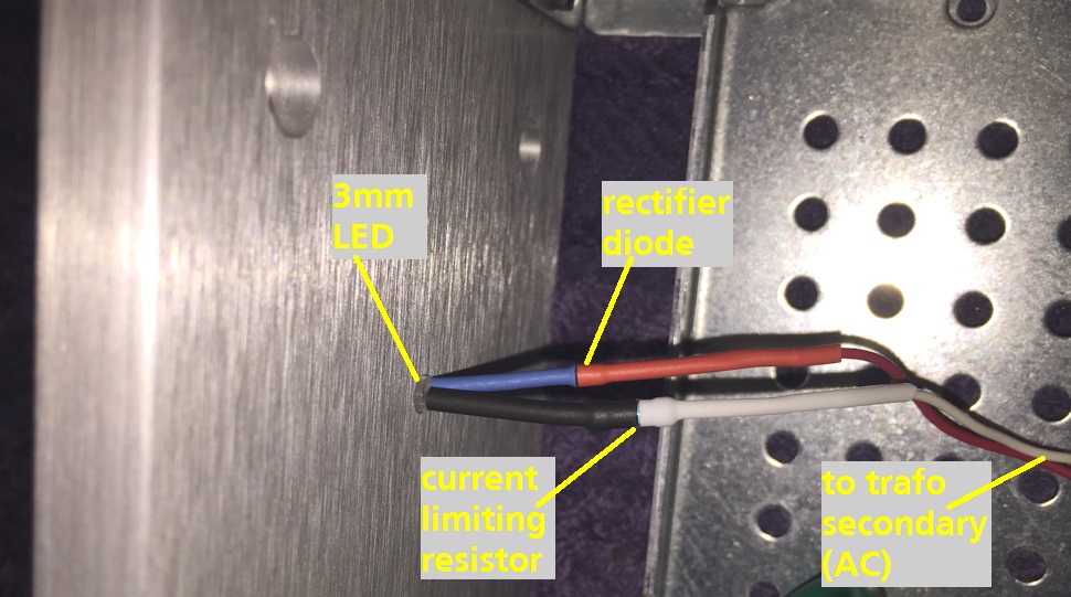
I didn't include any filtering, and I didn't see any flickering. I like this arrangement because the LED goes dark instantaneously, it is not connected to any filter capacitors that must discharge before the LED can extinguish. So when I flip the AC mains power switch to OFF, the LED goes out with zero delay.
Every time I post this photo, people go mental when I mention that the rectifier diode in the picture is a 1N3595. I have a drawer full of these and I use them a lot. If you don't have a drawer full of 1N3595s, don't fear: you can use any diode whose max reverse voltage spec is at least 2X the transformer secondary voltage.
_
Last edited:
The other view is that in various situations the LED bleeds caps and that slowing decaying light shows the caps to be discharged. When fed DC they will not flicker in a lifetime 🙂 I have never noticed flickering with LEDs on 50 Hz pulsating DC (except when filming) and I would also not loose sleep over it either but a cap won't harm. A light bulb filament glows after the voltage is gone and it lighted on both halves of the sinus so the flickering effect is likely less than with using pulsating DC on LEDs.
Could you explain post #11 a few pages ago with the double LED? In post #30 you use the suggested series diode.
Could you explain post #11 a few pages ago with the double LED? In post #30 you use the suggested series diode.
Last edited:
I'm not him, but posts #11 and #30 show different approaches. While #30 follows your suggestion, #11 means two diodes in parallel, back to back. I'd prefer the latter one, as the two diodes protect each other against excessive reverse voltage, whereas in a rectifier arrangement the reverse voltage distribution depend on the reverse impedances, or currents, of both diodes. I don't know fur sure as the reverse currents aren't mentioned in LED datasheets, but if a LED were the »better« rectifier with lower reverse current, the reverse voltage drop over it might exceed the ratings.
A common small signal diode back to back with the LED will do the same trick, of course, but can't be hidden that easily with just some shrinking tube.
Best regards!
A common small signal diode back to back with the LED will do the same trick, of course, but can't be hidden that easily with just some shrinking tube.
Best regards!
KP check the datasheet of the 1N3595, it has world-beating reverse leakage in the thru hole category. Also remember that the current limiting resistor is present, so even if the 1N3595 becomes a short circuit, the amount of current available to do damage, isn't large.
I'm not him, but posts #11 and #30 show different approaches. While #30 follows your suggestion, #11 means two diodes in parallel, back to back.
A bicolor bidirectional LED as suggested has 2 LEDs in antiparallel. These bicolor bidirectional LEDs often have 2 different colors 😀
Last edited:
It has been done since ... forever ... carrying Mains voltage to *front panel* Neon bulb indicators (I guess mains already classifies as dangerous voltage) AND much higher (hundreds of volts) DC voltage for Mains and Standby voltage pilot lights.why would anyone route higher voltage wires to a front panel just for a LED? No sane person would drop 250V over just 1 resistor and accept the risk...... It is simply bad design and unsafe.
Mounted on their own or inside illuminated rocker switches.
Should check some Underwriter´s Actuary tables to learn how many deaths that dangerous practice has caused.
FWIW a very common Neon bulb dropping resistor value is 100k or thereabouts, 1/4 W seems to be a popular rating, again didn´t hear about burning homes or electrocution caused by them.
In my tube amp, for power indicator (the tubes are in a screened cage) I merely used a blue LED with a 4.7K resistor and 1N4004 diode in series with the LED, fed from the 6.3V filament line.
Nice, simple, safe, and the LED isn't blindingly bright.
Nice, simple, safe, and the LED isn't blindingly bright.
A bicolor bidirectional LED as suggested has 2 LEDs in antiparallel. These bicolor bidirectional LEDs often have 2 different colors 😀
You're right. Most common are a green and a red chip in one LED. The result when fed with AC is a yellow one 😉.
Best regards!
In my tube amp, for power indicator (the tubes are in a screened cage) I merely used a blue LED with a 4.7K resistor and 1N4004 diode in series with the LED, fed from the 6.3V filament line.
Nice, simple, safe, and the LED isn't blindingly bright.
Funny, I use a 51k dropper from 12V for my blue LED and it's still "land a plane" bright!
It has been done since ... forever ... carrying Mains voltage to *front panel* Neon bulb indicators (I guess mains already classifies as dangerous voltage) AND much higher (hundreds of volts) DC voltage for Mains and Standby voltage pilot lights.
Mounted on their own or inside illuminated rocker switches.
Should check some Underwriter´s Actuary tables to learn how many deaths that dangerous practice has caused.
FWIW a very common Neon bulb dropping resistor value is 100k or thereabouts, 1/4 W seems to be a popular rating, again didn´t hear about burning homes or electrocution caused by them.
You probably forget that panel mount ready made LEDs with built in resistor have very thin wires with very thin isolation. If it says something, it is 24 AWG. A long time ago somewhat thicker wire was used with thicker isolation for neon lights and distances/clearance were larger as well as these needed somewhat higher voltages than 1.6V to glow so I guess you combine two things that are separate. Anyway, route those LEDs the way you want them and choose the highest B+ you can find for optimal engineering. IMHO panel mount ready made LED pilot lights with built in resistor/diode are best connected to LV filament windings, certainly considering the DIY level I see by many.
@kodabmx: the first blue LEDs needed far more current and had a different blue color than currently produced blue LEDs. I have an amount of the older, then very expensive, blue LEDs and they need more current than their equally old green/amber/red brothers. Wiseoldtech probably has wise old blue LEDs 🙂 When the first blue LEDs came out there also existed fake blue LEDs with a tiny light bulb in them... On the other hand: your blue LED seems to glow bright at 0.158 mA which is a miracle 😉 At 120V the current would be 2.27 mA
You're right. Most common are a green and a red chip in one LED. The result when fed with AC is a yellow one 😉.
Best regards!
Yes. Mark Johnson probably likes the mix at 120 frames per second.
Last edited:
As jean-paul has already mentioned, yes, the blue LED in my tube amp is from around 2002.
And yes, the LED's I recently stocked are much more sensitive.
And yes, the LED's I recently stocked are much more sensitive.
- Home
- Amplifiers
- Tubes / Valves
- LED power indicator from heater circuit