Hiya guys! My first post on DIYAUDIO.
I am wanting to build a tone control. The chip solutions sure look easy, and based upon their data sheets, they look like awesome performers. My intuition would make me think a discrete design would be better, but I'm not sure if my construction abilities could produce a noise free discrete circuit. I think it's time for some facts and info.
First off, since I am a noob, could you point me at FAQs for perfboard layout/wiring/construction do's and don'ts. I do know about star/single point grounding rules.
- So, which chip is better (if "better" can be applied to these chips") ) ?
) ?
- Can I get away with the circuits published in the data sheets?
- I saw a kit built around the TDA1524 for ~$25: http://www.electronickits.com/kit/complete/ampl/k100.pdf
I don' think I could build it for that cost on my own. Is this a viable option?
Any other advice would be greatly appreciated. Thanks guys !!!
I am wanting to build a tone control. The chip solutions sure look easy, and based upon their data sheets, they look like awesome performers. My intuition would make me think a discrete design would be better, but I'm not sure if my construction abilities could produce a noise free discrete circuit. I think it's time for some facts and info.
First off, since I am a noob, could you point me at FAQs for perfboard layout/wiring/construction do's and don'ts. I do know about star/single point grounding rules.
- So, which chip is better (if "better" can be applied to these chips
) ?- Can I get away with the circuits published in the data sheets?
- I saw a kit built around the TDA1524 for ~$25: http://www.electronickits.com/kit/complete/ampl/k100.pdf
I don' think I could build it for that cost on my own. Is this a viable option?
Any other advice would be greatly appreciated. Thanks guys !!!
Greetings
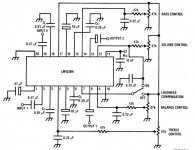
Wow I thought I was the only one using the LM1036 with DC volume and tone controls for creating my preamps. It's good to know that there is still an interest in this little capable IC.
I have been using this preamp IC in many of my homebrew amplifiers and most recently in modding certain boomboxes. My most recent mod was the Memorex MX3851 boombox, which some of you may still see on your Wal-Mart shelves. I'm sure some of you are Googling this model now and saying to yourselves "Ewwww that cheap junky thing??" Lol. Let's just say I like challenges.
I had to scrap the junky 2.5W/ch channel amp, ditch the embarrassingly junky transformer, crappy tinny PC beep speaker quality drivers, and scrap the laughingly horrible implementation of bass boost all in place of a new amplifier IC using the STA540, a gutted 12V 5A switching power supply purchased from ebay, an additional preamp circuit consisting of the LM1036, and the absolute most challenging part of all, finding 3" round full range speakers that can handle more than 25 watts as well as using a dremel to aid in mounting the speakers.
---Disadvantages---
The past challenges I have ran into with the LM1036 and a power amplifier is that upon power cutoff on the preamp you will hear an annoying pop. Also you need to make a very critical choice of output capacitors on the preamp output stage or otherwise you might get what I call the "idle motorcycle engine effect" when cranking up the volume. That's when you will a rhythmic popping sound like an idled motorcycle in the background, not very loud, but darn annoying as heck. To cure the turn off pop I had to create an RC filter 1st for the preamp, and then create a transistor based delay switch-off circuit so that upon powering off the power amp the preamp will retain power for 2 seconds and then power off.
---Advantages---
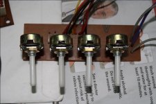
Now as far as the quality goes I am quite impressed. The quality of the LM1036 overshadows the minor headaches and disadvantages of the LM1036. It completely outdoes any of my previous opamp based preamps that I have mastered. The boost quality is just phenomenal, as long as you select the correct bass and treble capacitors and match the boosting with the dynamics of your speakers. There is none of that AC humming, as long as you use the correct grounding procedures, and it is quiet. The highs are crystal clean and crisp and the bass is not at all muddy. Now if you really like heavy bass it has a loudness compensation that really takes the bass much farther, although this is where you have to make sure the speakers can handle the load from your power amp. I use the loudness compensation in place of the bass boost on the Memorex boombox. I also use the DC volume control vs the conventional dual gang method mostly because it keeps both channels balanced upon volume changing. i also only need single gang pots for the bass, treble, and balance which also helps to cut down cost of parts.
---Design Skill Level---
As far as putting together the LM1036 circuit the datasheet reference circuit is good enough. It gives you plenty of information to make a fully working circuit. The only things you may want to play with are the bass/treble capacitors and the output capactors. Regarding the output capacitors if you choose too high of a value on you may run into that "idle motorcycle engine effect" as well as harsh DC filtering. If you choose too low of a value then you may risk sacrificing the amount of bass being boosted. Also if you use your standard Radio Shack copper clad breadboard it may take you anywhere from 2-4 hours of assembly. It's a very simple circuit although it's the cramming of parts in a small space that requires you to spend a lot of time being a little creative without being sloppy.
Wow I thought I was the only one using the LM1036 with DC volume and tone controls for creating my preamps. It's good to know that there is still an interest in this little capable IC.
I have been using this preamp IC in many of my homebrew amplifiers and most recently in modding certain boomboxes. My most recent mod was the Memorex MX3851 boombox, which some of you may still see on your Wal-Mart shelves. I'm sure some of you are Googling this model now and saying to yourselves "Ewwww that cheap junky thing??" Lol. Let's just say I like challenges.
I had to scrap the junky 2.5W/ch channel amp, ditch the embarrassingly junky transformer, crappy tinny PC beep speaker quality drivers, and scrap the laughingly horrible implementation of bass boost all in place of a new amplifier IC using the STA540, a gutted 12V 5A switching power supply purchased from ebay, an additional preamp circuit consisting of the LM1036, and the absolute most challenging part of all, finding 3" round full range speakers that can handle more than 25 watts as well as using a dremel to aid in mounting the speakers.
---Disadvantages---
The past challenges I have ran into with the LM1036 and a power amplifier is that upon power cutoff on the preamp you will hear an annoying pop. Also you need to make a very critical choice of output capacitors on the preamp output stage or otherwise you might get what I call the "idle motorcycle engine effect" when cranking up the volume. That's when you will a rhythmic popping sound like an idled motorcycle in the background, not very loud, but darn annoying as heck. To cure the turn off pop I had to create an RC filter 1st for the preamp, and then create a transistor based delay switch-off circuit so that upon powering off the power amp the preamp will retain power for 2 seconds and then power off.
---Advantages---
Now as far as the quality goes I am quite impressed. The quality of the LM1036 overshadows the minor headaches and disadvantages of the LM1036. It completely outdoes any of my previous opamp based preamps that I have mastered. The boost quality is just phenomenal, as long as you select the correct bass and treble capacitors and match the boosting with the dynamics of your speakers. There is none of that AC humming, as long as you use the correct grounding procedures, and it is quiet. The highs are crystal clean and crisp and the bass is not at all muddy. Now if you really like heavy bass it has a loudness compensation that really takes the bass much farther, although this is where you have to make sure the speakers can handle the load from your power amp. I use the loudness compensation in place of the bass boost on the Memorex boombox. I also use the DC volume control vs the conventional dual gang method mostly because it keeps both channels balanced upon volume changing. i also only need single gang pots for the bass, treble, and balance which also helps to cut down cost of parts.
---Design Skill Level---
As far as putting together the LM1036 circuit the datasheet reference circuit is good enough. It gives you plenty of information to make a fully working circuit. The only things you may want to play with are the bass/treble capacitors and the output capactors. Regarding the output capacitors if you choose too high of a value on you may run into that "idle motorcycle engine effect" as well as harsh DC filtering. If you choose too low of a value then you may risk sacrificing the amount of bass being boosted. Also if you use your standard Radio Shack copper clad breadboard it may take you anywhere from 2-4 hours of assembly. It's a very simple circuit although it's the cramming of parts in a small space that requires you to spend a lot of time being a little creative without being sloppy.
Greetings
The past challenges I have ran into with the LM1036 and a power amplifier is that upon power cutoff on the preamp you will hear an annoying pop. Also you need to make a very critical choice of output capacitors on the preamp output stage or otherwise you might get what I call the "idle motorcycle engine effect" when cranking up the volume. That's when you will a rhythmic popping sound like an idled motorcycle in the background, not very loud, but darn annoying as heck.
Hi, can you give the solution for the "idle motorcycle engine effect". I was thinking to throw this chip away for the noise. Thanks in advance.
The "idle mocicle effect" is most likely "motorboating sound", caused by insufficient powersupply decoupling between power- and pre-amps. Heavier electrolytics may solve the problem but often, especially in DIY, it is poor grounding technique (ground-loops).
The "pop" on power-down is solved by an AC powered relay that cuts the line to the speakers (insert a resistive load instead to prevent oscillation?) befor the DC rail goes down.
E
The "pop" on power-down is solved by an AC powered relay that cuts the line to the speakers (insert a resistive load instead to prevent oscillation?) befor the DC rail goes down.
E
Ok, thanks dude. I got your point for the POP noise during switch off. But need more help in "motorboating sound". Please give me the diagram or parts detail you used for stopping this. If you have changed any Cap value or something else...The "idle mocicle effect" is most likely "motorboating sound", caused by insufficient powersupply decoupling between power- and pre-amps. Heavier electrolytics may solve the problem but often, especially in DIY, it is poor grounding technique (ground-loops).
The "pop" on power-down is solved by an AC powered relay that cuts the line to the speakers (insert a resistive load instead to prevent oscillation?) befor the DC rail goes down.
I liked the sound quality and BOOST CUT level of the chip very much but the noises.
The system I used:
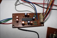
1. On tone control PCB 0.1 mfd and 100 mfd caps for filtering.
2. Tone control Board PSU has 16V DC > 1000 mfd/25V > LM7812 > 220mfd/25V and .1 mfd
3. Tone control board input cap = 1 mfd/63V electrolytic, output cap 10mfd/40V electrolytic.
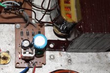
4. Power amp used = LM4766T with +-28V supply.
Also I am attaching the files I followed for this preamp.
Attachments
Ok, thanks dude. I got your point for the POP noise during switch off. But need more help in "motorboating sound". Please give me the diagram or parts detail you used for stopping this. If you have changed any Cap value or something else...
I liked the sound quality and BOOST CUT level of the chip very much but the noises.
The system I used:
1. On tone control PCB 0.1 mfd and 100 mfd caps for filtering.
2. Tone control Board PSU has 16V DC > 1000 mfd/25V > LM7812 > 220mfd/25V and .1 mfd
3. Tone control board input cap = 1 mfd/63V electrolytic, output cap 10mfd/40V electrolytic.
4. Power amp used = LM4766T with +-28V supply.
Also I am attaching the files I followed for this preamp.
Hi diptangshu,
I think I can be of some help with your preamp circuit. It definitely sounds like you have a relatively decent setup, we just need to get you past the "motorboating sound" issue.
This is actually somewhat simple to achieve. It's just a matter of changing 4 capacitors.
Now for the preamp input caps I used a 1MFD electrolytic capacitor. For the preamp output capacitors (this is where trial and error may come in) In my setup I went from a 10MFD to a 0.47MFD electrolytic capacitor (I had a choice of either 0.33MFD or 0.47MFD). I know it may seem like a small MFD value but trust me on this one. Someone may be able to explain the technical reasoning behind this better than I can but here is what i have observed:
When i use a higher MFD value, just enough to make the annoyance somewhat stop, I have noticed that when playing a music track with a good 'pop' type bass beat (not a rumbling low boom type bass), I have noticed the speaker cone wobbling in an unusual way, kind of like a bouncy car suspension. It has a ripple effect to heavy beats. It really was supposed to be an instantaneous beat. If i cranked up the volume to a relatively loud level during these beats it would once again start that annoying 'motorboating sound' once again as i turned it back down. I've also noticed that the 'motorboating sound' is sort of like a feedback. Me being a late 70's and early 80's home audio and ghetto blaster "boombox" fanatic I know this ultra low wobbling of the speaker cone during beats like that usually would require a subsonic filter. The cheap and easy way of creating a subsonic filter would be to just lower the preamp output capacitor values. SO instead of my initial choice of using a 10MFD capacitor, i lowered it to 0.47MFD.
In addition of killing that annoying issue I took the time to put a zener diode on the the VCC+ line and added a filter capacitor (1000 MDF) on the V+ power input for the preamp (all on the preamp PCB) to further isolate any possible voltage feedback to the power amp. I'm not sure if that is verbally correct but i'm sure you and most can somewhat understand what I am trying to say. All I can say is that it worked for me and has not bothered me ever since.
Try those values and let me know if that helped you out. Also try adding the zener diode on the VCC+ voltage line input to the preamp for the added isolation.http://www.diyaudio.com/forums/images/smilies/smile.gif
The "idle mocicle effect" is most likely "motorboating sound", caused by insufficient powersupply decoupling between power- and pre-amps. Heavier electrolytics may solve the problem but often, especially in DIY, it is poor grounding technique (ground-loops).
The "pop" on power-down is solved by an AC powered relay that cuts the line to the speakers (insert a resistive load instead to prevent oscillation?) befor the DC rail goes down.
E
Normally I would use a relay but this being a battery operated boombox I wanted to go a different route while conserving "some" energy. I just simply used my transistor switching delay circuit to keep the power to the preamp on 5 seconds after the power amp's stand-by circuit kicks on.
I am, however, open to any decent ground loop solutions that you might have. My Memorex boombox is not quite a finalized project yet.
Hi Kamal,hi
this is kamal
try this circuit this is best choice for home use amplifiers
I have used this basic circuit in the past, which is known as a Bandaxall tone control circuit. After experimenting with the LM1036 I have given up totally on the Bandaxall tone control circuit for the following reasons:
Aside from it's circuit simplicity the Bandaxall tone control circuit does not create a true 'boost' in the tone control. In fact it technically preamplifies the incoming audio and then "shelves" the frequencies. To better explain the "shelving" that I am talking about, think of this circuit as a high and low pass filter.
The so called 'boost' ability is very weak when compared to the LM1036.
That same so-called 'boost' in the focused frequency range has a more hollow sounding end result.
The LM1036 uses several internal feedback techniques to actually create a true boost in the bass, treble, and loudness.
Now my reason behind requiring this phenomenal tone boosting is that I, as stated before, I come from a generation of late 70's, early to late 80's home audio and boomboxes, where if you cranked up the bass your stereo would seriously rock the entire house, maybe even causing your woofers to pop (where the voice coil of the woofer whacks the back of the speaker magnet internally) and when you cranked up the treble you could hear a lot of fine instrument detail crisp and clearly, like hearing a stick or brush hitting a tom tom, cymbal, or a high hat, the strumming of the guitar strings, or even the detail of glass breaking. Back then you were able to hear such detail from a 40 or 60 watt per channel brand name stereo receiver connected to standard average off the shelf speakers, without needing to spend a ridiculous amount for high end speakers.
Now compare a 65 watt per channel (we'll say a vintage Marantz SR-5100 stereo receiver) to any 2 channel receiver from today. You will hear exactly what I mean about the difference.
Remember even when boomboxes used to sound like miniature rack stereos instead of todays boomboxes that sound cheap. It's all in the preamp.
My whole point of using a LM1036 is that it is the absolute lowest cost method available for giving a sub 100 watt per channel power amp much bigger sound. I used this circuit in my last integrated amplifier project using a class D amplifier. The sound can almost match the quality of a Proton D930 or NAD equivalent stereo receiver released back in the 80's. I'm still trying to implement my own dpd (dynamic power on demand) circuit.
Now if you are of the 'high end audio' crowd where tone controls don't really play that much of a part in your daily listening, and/or already have spent a ridiculous amount on your speakers then yes the Bandaxall preamp would suffice.
I do understand to some that the LM1036 might seem a bit cumbersome, frustrating, or a bit annoying upon implementation. Once you work out all of the coupling and power supply kinks & quirks, you will be greatly rewarded with a very awesome sounding amplifier. Trust me I should know. I have been using the LM1036 for almost 2 years now.
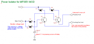
By the way here is my very simple power isolator circuit that I have used. This circuit prevents those annoying oscillations when connecting the power amp to the LM1036 based preamp. I have found that my problems was due to some type of feedback that required some form of power isolation without taking the dc-to-dc converter approach.
How I came to this conclusion was that all of my problems went away when i temporarily used a totally separate DC power supply for the preamp.
How I came to this conclusion was that all of my problems went away when i temporarily used a totally separate DC power supply for the preamp.
Attachments
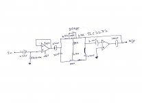
you can use these tone controls. LF353 is tested but the mid band control has little tuning effect. You can try to manage it. I have made it 6 yars ago and working fine. the PCB is not tested, please check it thoroughly. FET tone control has no PCB design.Hai frineds,
plz send me any other best tone control circuit for STK4142 IC. I am also used tda1524 and lm 1036.
kamal
What is your experience on TDA1524 and LM1036?
Attachments
Major Update
I have just stumbled upon an even better fix for the "motorboating" noise issues, but at the same time improving audio quality. I stumbled upon this from a Class D audio forum. The answer to all of these problems is using WIMA audio capacitors. They are designed specifically for audio purposes.
Originally I just wanted to improve the sound quality on my STA540 class AB chip amp and the LM1036 based preamp. I accidentally discovered 90% of other annoying issues were solved by switching to them. I also discovered a phenomenal improvement of frequency response on the bass side, and the highs are a lot more crisp and detailed. I originally was going to implement a dynamic bass feedback type setup to boost the volume of low frequencies well below 90Hz, but with these WIMA capacitors I don't need to do any such thing. Lastly I also accidentally discovered a fix for another issue I had. When the output becomes overdriven by excessive bass, well below power amp clipping, the power would cut off and then cut back on. Switching to WIMA audio capacitors now allow me to crank up the audio output well past clipping.
What I did was that on my STA540 amp board I bypassed the original power amp input capacitors and connected it's input to the newly replaced WIMA 4.7uf capacitor on the output of the LM1036 preamp board. I also went a step further and replaced the preamp input capacitors with the same 4.7uf WIMA capacitors as well.
I also took the time to remove any other electrolytic capacitors along all audio output paths (AM/FM tuner board output and CD player output) and replaced them with WIMA capacitors. Wow what an amazing difference the sound quality of this little boombox has. Better and louder than ever.
My conclusion is that using electrolytic capacitors of any type on an audio path is pure evil. They instantly degrade your sound. You may not notice now but once you switch you WILL hear the difference. I don't even get power down thumps when the tuner board or CD player powers down anymore. Now one disadvantage about WIMA capacitors are that THEY ARE NOT CHEAP. They usually run from $0.87-$4.00 USD per capacitor, however I personally think they are totally worth it if you are picky like me when it comes to audio quality. If you can't justify spending a little extra on WIMA capacitors then at least use film or any non polarized capacitors.
noisy chip
Hi all.
I have built his tone control and it works very well. Although the chip seems to have some inherit hiss noise which gets carried through the power amp and out the speakers. In a quiet room you can just hear it at full volume. To me this is not really acceptable. 80dB s/n ratio I thought would have been more quiet. The TDA1524 is much worse.
Can any on confirm about the hiss noise of these chips?
Regards
Billy D...
- Status
- This old topic is closed. If you want to reopen this topic, contact a moderator using the "Report Post" button.
- Home
- Source & Line
- Analog Line Level
- LM1036 vs TDA1524 vs Other