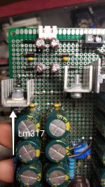
Hi, I'm building a simple dual rail power supply using a center tapped 15V transformer and currently have issues with a Lm 317 regulator - to cut the story short - there's no voltage drop across it.
The supply output reads +20V/-15V. Tested with no load on either rail. I've double checked used resistors, solder joints and schematics, it seems to be in order. The other regulator, Lm337, is doing a fine job at 15 V.
Does anyone have a recommendation on where to start troubleshooting?
Regards,
Stefan
Attachments
You could post the schematic, check if the path from ADJ to ground is open or OK, check for shorts from input to output or from the output to ADJ, calculate if the feedback network draws at least the 10 mA minimum load current.
Be aware that the perfboard you use has plated-through holes. If you do not take care, you can easily create unwanted connections from the top side, with heatsinks, exposed conducting parts, etc.
Check the input/output continuity: if you find 0 ohm, locate the culprit
Check the input/output continuity: if you find 0 ohm, locate the culprit
Here's the schematics (https://sound-au.com/project05.htm - Figure 2). Those exact values are used on my board.
ADJ to ground is connected through two resistors in parallel.
I've tried adding 560R between the output and the ground, minor voltage drop, but it still reads close to 20v.
Heatsinks are both insulated and not in contact with other parts.
Shouldn't there be a blown fuse, magic smoke, or at least some heat at the heatsinks, or the board if there's a short? What confuses me is why the negative rail is working fine, it's a mirror image of the other one (except for the regulator connection).
Attachments


It is, here's the correct one:I see a schematic with a 7815 and 7915 as figure 2. Wrong link?
https://sound-au.com/project05d.htmFigure one, with identical values as presented.
Is the diode in the right way (cathode to input for the LM317)?
What are the DC voltages across R3, and also across R4?
For 15VDC output, R3 should have 1.25V across it, and R4 should have 13.75V.
Are you certain that these resistors have the right ohm values?
Do you know that the LM337 and LM317 have different pinouts?
What are the DC voltages across R3, and also across R4?
For 15VDC output, R3 should have 1.25V across it, and R4 should have 13.75V.
Are you certain that these resistors have the right ohm values?
Do you know that the LM337 and LM317 have different pinouts?
Last edited:
I'm aware of that: input on lm317 is connected to pin3, output on pin2 and a diode in direction from pin2 to pin3. Power to lm337 is connected on pin 2, diode from pin3 to pin2.
Here are the voltages, interesting, they're different:
R3 1.2 on 337 and 1.6 on 317
R4 13.5 on 337 and 18.5 on 317!
Here are the voltages, interesting, they're different:
R3 1.2 on 337 and 1.6 on 317
R4 13.5 on 337 and 18.5 on 317!
Attachments

They have to be different, since the 317 output voltage is 20V. The question is, why are they different.
It's possible that either the connections for R4 are bad, or that R4 is open or the wrong value (too high).
It's possible that either the connections for R4 are bad, or that R4 is open or the wrong value (too high).
Last edited:
It's interesting that the voltage across R3 is way too high, though. ADJ disconnected from the voltage divider R3-R4? Or a hard short from input to output?
The only reason I could see is that I somehow messed up the resistor values. However, by looking at the markings (visible on some of the pictures), they do seem identical, don't they?They have to be different, since the 317 output voltage is 20V. The question is, why are they different.
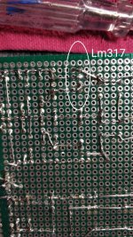
I'm not exactly sure what you mean by disconnected. Here's another picture with marked components on the underside of PCB, hope it helps with the answer.It's interesting that the voltage across R3 is way too high, though. ADJ disconnected from the voltage divider R3-R4? Or a hard short from input to output?
Attachments

With everything off, when you measure the resistance from the point where R3 and R4 are connected to the ADJ pin of the LM317, do you find a value well below 1 ohm? And do you measure a resistance well above 1 ohm between the IN and OUT pins of the LM317?
From the solder joint between r3 and R4 to ADJ - no resistance. From ADJ to GND almost 1.1 kOhm. From input to output pin of Lm317 - 1.4 ohm.With everything off, when you measure the resistance from the point where R3 and R4 are connected to the ADJ pin of the LM317, do you find a value well below 1 ohm? And do you measure a resistance well above 1 ohm between the IN and OUT pins of the LM317?
Lm337 measures no resistance between input and output pins. Why the difference?
What do you mean by no resistance, near zero resistance or very large resistance? (This may seem like a silly question, but if you mean near zero, I don't understand how the LM337 can work.)
Multimeter reads 0.L. I'm not quite sure. I recon it's the latter (by shorting the probes, it reads 0.000).What do you mean by no resistance, near zero resistance or very large resistance? (This may seem like a silly question, but if you mean near zero, I don't understand how the LM337 can work.)
I have lm337 spares, probing pin2 to either of other two pins reads 0L. The same situation is with 317 I've used in single rail 5v (that actually works), again, input / output reads 0L.
Only with the 317 that outputs wrong voltage, there's a ohm and a half resistance between input and output pins.
- Home
- Amplifiers
- Power Supplies
- Lm317 issues/not working?