UPDATE 11-9-2022: Critical update to the project in the post #18. Major layout error involving LM337 was fixed!
Update 12-24-22: Project was revisited and redesigned from the scratch.
The idea was to make a single board that will include it all:
To finish the project you would need:
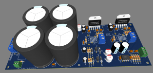
Board size is 200mm x 75mm.
Input level for this amp is set to +4 dBu - typically found in professional audio equipment.
Input buffer OPAMP can be NE5532, LM4562, or any other.
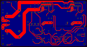
Attached are schematics, PCB design, simulation file, and gerber files.
Update 12-24-22: Project was revisited and redesigned from the scratch.
The idea was to make a single board that will include it all:
- two channels of inverted LM3886 amps
- input buffer OPAMP
- rectifier bridge
- filter caps
- power delivery for the OPAMP
To finish the project you would need:
- case
- heatsink
- transformer
- RCA inputs, binding posts outputs
- power plug (preferrably with EMI filtering)
Board size is 200mm x 75mm.
Input level for this amp is set to +4 dBu - typically found in professional audio equipment.
Input buffer OPAMP can be NE5532, LM4562, or any other.
Attached are schematics, PCB design, simulation file, and gerber files.
Attachments


Last edited:


Since you use input op-amp and the circuit has already the power supply needed for this, I would recommend to add DC-servo circuits.
This will eliminate two large electrolytics per channel.
This will eliminate two large electrolytics per channel.
Not sure why I should get rid of main caps - are you talking about C28, C29?Since you use input op-amp and the circuit has already the power supply needed for this, I would recommend to add DC-servo circuits.
This will eliminate two large electrolytics per channel.
Or C7, C8?
Something like this? - https://www.hypex.nl/img/upload/doc/an_wp/WP_The_G_word.pdf
The signal caps C7 - C8.
yes, similar to U3A in page 12.
Something like this? - https://www.hypex.nl/img/upload/doc/an_wp/WP_The_G_word.pdf
yes, similar to U3A in page 12.
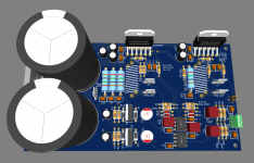
Here is the version without the capacitor but with the servo to correct for the any DC offset at the input of the LM3886. Attached are the simulation screenshots and simulation file.
Attachments


Here is inverted LM3886 with buffer as a voltage follower (no gain) and with servo instead on DC blocking capacitors. PCB and schematics attached.
Input level for this one should be +4 dBU.
Open source gerber files attached.
Input level for this one should be +4 dBU.
Open source gerber files attached.
Attachments


Once I'm on it, I decided to redesign layout for 2CH AMP from the first post. It has sensitivity of -10dBV. Open source gerber files are attached.
Attachments


Here is 2CH AMP +4 dBU input level with DC blocking capacitors.
Open source gerber files attached.
Open source gerber files attached.
Attachments


Major mistake in the schematics was fixed!Here is inverted LM3886 with buffer as a voltage follower (no gain) and with servo instead on DC blocking capacitors. PCB and schematics attached.
Input level for this one should be +4 dBU.
Open source gerber files attached.
Input buffer opamps were incorrectly wired - feedback was taken from the opamp's output and connected to the non-inverting input - that was incorrect! Fixed that and minor layout issues in this open source gerber file and schematics.
Attachments


Last edited:
Nice to see some sensible feedback resistor values on the op amps.
I had a circuit where I had 100k in the feedback loop and I sometimes got awful noises on the output.
I had to add small cap across 100k to fix it.
I really should have used lower value resistors but I needed high input impedance as it was a differential amplifier so couldnt.
I had a circuit where I had 100k in the feedback loop and I sometimes got awful noises on the output.
I had to add small cap across 100k to fix it.
I really should have used lower value resistors but I needed high input impedance as it was a differential amplifier so couldnt.
Nice to see some sensible feedback resistor values on the op amps.
I had a circuit where I had 100k in the feedback loop and I sometimes got awful noises on the output.
I had to add small cap across 100k to fix it.
I really should have used lower value resistors but I needed high input impedance as it was a differential amplifier so couldnt.
I found this handy calculator for Johnson noise - https://www.daycounter.com/Calculators/Thermal-Noise-Calculator.phtml
100k resistor will produce -104.0 dbv or -102.7 dbu noise (that is over 20khz range with temp of 20 degrees C)
I figured it is better to insert an opamp in the circuit rather than set the gain of the main chip amp (lm3886) to, say, 75 V/V.
If opamp buffer is used, resistors in the feedback can be 3K for buffer and 20K for the LM3886. There is also 100R and 1K resistors in the signal path, but overall, as far as johnson noise, I think it is the optimal way to do it.
So in total I had designed and simulated four circuits for inverted LM3886:
Out of all four, my favorite is the one with DC blocking capacitor and +4 dBU input sensitivity. It allows a room to grow in the future with possibly a good quality preamp, or to use it with professional equipment like sound interfaces.
I plan on adjusting schematics to be able to use with switching power supply. For that I would just have to remove rectifier bridge and main filtering capacitors. That is hopefully coming soon.
- -10 dBV input sensitivity with DC blocking capacitor on the output of LM4562 buffer
- +4 dBU input sensitivity with DC blocking capacitor on the output of LM4562 buffer
- -10 dBV input sensitivity with DC servo
- +4 dBU input sensitivity with DC servo
Out of all four, my favorite is the one with DC blocking capacitor and +4 dBU input sensitivity. It allows a room to grow in the future with possibly a good quality preamp, or to use it with professional equipment like sound interfaces.
I plan on adjusting schematics to be able to use with switching power supply. For that I would just have to remove rectifier bridge and main filtering capacitors. That is hopefully coming soon.
Last edited:
-10 dBV input sensitivity with DC servo application of the inverted LM3886 is little tricky. Because there is a gain of 4x of the input buffer LM4562, the DC that is being presented to the input of the LM3886 is around 170mV (according to LTSpice simulator). To be able to correct that much voltage, servo circuit had to be adjusted by changing resistor values. Schematics is below.
Also, since it takes about two seconds for the servo to start working, there should be some sort of protection relay that would disconnect speakers from the amplifier output while the servo circuit is settling.
Open source gerber files are attached.
Also, since it takes about two seconds for the servo to start working, there should be some sort of protection relay that would disconnect speakers from the amplifier output while the servo circuit is settling.
Open source gerber files are attached.
Attachments


Last edited:
I have redesigned board with the input sensitivity of 2Vrms. Reason behind that is output level of Topping DACs into RCA output is 2Vrms. Other companies seems to be designing products with this output level too.
Attachments


This whole project has been revisited and redesigned from the ground up. Changes made include adding space for two more 35mm capacitors, using TO-92 regulators, better ground planes, and other minor layout improvements.
The first post was updated to include gerbers for +4dBu input level.
This post will have files for -10 dBV level of input.
Zipped is TINA-TI simulation file.
The first post was updated to include gerbers for +4dBu input level.
This post will have files for -10 dBV level of input.
Zipped is TINA-TI simulation file.
Attachments


Last edited:
Nice work. I always thought inverting was the way to go with the 3886. I built a few gainclones deadbug style inverting and always had good results.
- Home
- Amplifiers
- Chip Amps
- LM3886 inverted amplifier with opamp buffer board