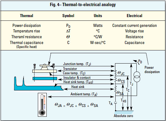
Links to equation used for determining the device junction temperature.
How to Select a Suitable Heat Sink
Power Transistors and Heat sinks
Application Note 90B DC POWER SUPPLY HANDBOOK
http://cp.literature.agilent.com/litweb/pdf/5952-4020.pdf
How to Select a Suitable Heat Sink
Power Transistors and Heat sinks
Application Note 90B DC POWER SUPPLY HANDBOOK
http://cp.literature.agilent.com/litweb/pdf/5952-4020.pdf
suggest adding beefy protection diodes across the input ( reverse bias ) and across the pass transistor (discharges excess output reactance at turn off ).
slow start?
remote sense?
dual current limit eg constant current with SC fold back override.
slow start?
remote sense?
dual current limit eg constant current with SC fold back override.
Hi Soeren Poulsen.
Sounds good and very welcome : ) I have built a few fx pedals and designed and built an valve amp, and pre amp pedal but both with very basic unregulated power supply and both times psu was purpose built. After throwing out my bed and turning my flat into a workshop (grin) i am now in possesion of a scope a dmm a junk box the size of my bathroom (as i live directly opposite a recycle yard) etching kits, and many other bits for my little hobby. But no bench supply of course! well it is half built, i have the 350v and the 12v and 6.3v done. I have a few big transformers taken from 150 and 300 watt hifi amps. One with three secondary windings, 60v center tap and two 15v. also from these amps are the big heat sinks. one that cooled the STK463 sterio amplifier, and some others. Anyway they are pretty big. i have some large pc psu fans too so the cooling and the raw voltage should not be a problem. Thank you
Sounds good and very welcome : ) I have built a few fx pedals and designed and built an valve amp, and pre amp pedal but both with very basic unregulated power supply and both times psu was purpose built. After throwing out my bed and turning my flat into a workshop (grin) i am now in possesion of a scope a dmm a junk box the size of my bathroom (as i live directly opposite a recycle yard) etching kits, and many other bits for my little hobby. But no bench supply of course! well it is half built, i have the 350v and the 12v and 6.3v done. I have a few big transformers taken from 150 and 300 watt hifi amps. One with three secondary windings, 60v center tap and two 15v. also from these amps are the big heat sinks. one that cooled the STK463 sterio amplifier, and some others. Anyway they are pretty big. i have some large pc psu fans too so the cooling and the raw voltage should not be a problem. Thank you
Last edited:
ps. I think Rod Elliott site is brilliant! i read through the designs with op amps and active filters articles a fe months ago and is where i gained the little knowledge i have to build op amp based pedals. Also the valve wizard was pretty helpful for the valve amps but i am only at the begining of my journey : )
Building a power supply is a great way to learn, however, after about 100 hours and $100-$200 what will you have?
I found this lab supply on ebay for about $30, Farnell TL30-2. You can series the two outputs and get 60V@2A, with voltage and current adjustable down to zero. I also found a schematic on line, incase it needs repair.
I found this lab supply on ebay for about $30, Farnell TL30-2. You can series the two outputs and get 60V@2A, with voltage and current adjustable down to zero. I also found a schematic on line, incase it needs repair.
An externally hosted image should be here but it was not working when we last tested it.
Last edited:
I can kinda see your point WSJ, but with a little more honesty than is probably needed, I spent a lot of time in two man pent house that the queen herself provided for me. There are much worse ways of spending time and money, and if it costs me $100 $200 or a $1000 or even ££££'s to enjoy learning and create, then I am happy to pay it my friend. 🙂
(Respectfully). oh, and thank you for the links WJS.
Plus...There is nothing quite like sitting back and looking at your work and saying.... I built that!
(Respectfully). oh, and thank you for the links WJS.
Plus...There is nothing quite like sitting back and looking at your work and saying.... I built that!
Last edited:
I can kinda see your point WSJ, but with a little more honesty than is probably needed, I spent a lot of time in two man pent house that the queen herself provided for me. There are much worse ways of spending time and money, and if it costs me $100 $200 or a $1000 or even ££££'s to enjoy learning and create, then I am happy to pay it my friend. 🙂
(Respectfully). oh, and thank you for the links WJS.
Plus...There is nothing quite like sitting back and looking at your work and saying.... I built that!
I agree, I built my first power supply in 1967: +/- 50V @ 10A, +/- 15V @ 1A and +24V. I invent a modified foldback current limit circuit, 1A below 49V then 49 to 50V @ 10 A. This design allowed the use of a single pass transistor for each 50V output. I was in Collage and did not have the money to buy 50power transistors.

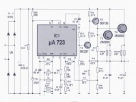
Here is the basic power supply circuit used in the uA723.
An externally hosted image should be here but it was not working when we last tested it.
REGULATED POWER SUPPLY USING 741 AND 2N3055 - HQEW.net
I would us a LM3886TF for the amplifier, it will operate with 94V supplies and it will drive the pass transistors without the need of a driver.
WSJ: I simply love that Farnell power supply. They are allmost indestructable! They got huge heatzinks, and lots of pass-transistors, to share the current. I have the schematic. i bought a 0 -30 Volt / 5 Amp a couple of Years ago for my dear friend, who is having an electricity installation business. He is a tough guy, and he has yet not fried the powersupply. I miss the schematic for that supply. But! we need to get jimmiegin to understand, why he needs the large heatzinks, and the many pass transistors. Jimmiegin, do You have the Ohm law circle with the 12 formulas? You need it in 1 X 1 meter size, hanging over Your bed! Seriusley!!!
WSJ: I simply love that Farnell power supply. They are allmost indestructable! They got huge heatzinks, and lots of pass-transistors, to share the current. I have the schematic. i bought a 0 -30 Volt / 5 Amp a couple of Years ago for my dear friend, who is having an electricity installation business. He is a tough guy, and he has yet not fried the powersupply. I miss the schematic for that supply. But! we need to get jimmiegin to understand, why he needs the large heatzinks, and the many pass transistors. Jimmiegin, do You have the Ohm law circle with the 12 formulas? You need it in 1 X 1 meter size, hanging over Your bed! Seriusley!!!
I agree with you. Motorola has a great app note, I will look for it later.
http://www.learnabout-electronics.org/Amplifiers/amplifiers51.php
Last edited:
WSJ: I just ran through the 3 links You postet in #21. I am overwhelmed. It is right what we need to start this project properly. Is anybody of us tough, making drawing? I can only use Paint, and it takes hell of a time. My first propersition: I will use 6 type 2N3773 series pass transistors, to spread the heat on several heatzinks, and give each pass transistor an emitter resistor of 1 Ohm, to be sure to share the current equal between all pass transistors. Next I would use a PNP transistor as the driver for the pass transistors, because instead of pushing further high to the base of a darlington coupled transistors, I am pulling the base of the driver downwards, when I want the output voltage to go higher. Any objections? Soeren Poulsen
WSJ: I need You to think this through: Take the "old faithfull uA723" look at the ordinary applications, where they make feed-back to the - input, and a variable voltage to the + input. Change that to: + input at constant +5 Volt from the reference voltage. A feed-back resistor of 10 KOhm from output back to - input. A 2 KOhm resistor from -input to a pot wiper, bottom pot to 0 Volt, top pot to 6 Volt from the reference voltage. Comments please
this one gets closer to Soeren's plan but cant quite go to zero V
> just design R26 to Vz for the highest input voltage to protect the IC and switch the rectifier input to lower XFMR taps.
> just design R26 to Vz for the highest input voltage to protect the IC and switch the rectifier input to lower XFMR taps.
Attachments
Last edited:
I'm working right now and will answer your questions later.
Go to the ExpressPCB - Free PCB layout software - Low cost circuit boards - Top quality PCB manufacturing and download the FREE CAD software.
No foolen it's FREE.
It's so easy to learn with all the help available. You can make and print schematics and layout boards for free. I use it all the time, they will make 3 top quality boards for about $50.
I do have an ohm's law wheel I copied from a book, I also have a box of huge heat sinks. Have been reading up on zener transistor regulators and Elliott sound article on heat sinks and the link in WSJ's last post. some Very useful/essential information. I now have A4 pages of notes from links and info given, schematics and my own searches on power supply design and so on. Thank you for all the info so far guys it is very much appreciated. I had no idea so much study would be involved.... But it's all good fun 🙂 I actually did throw out my bed to make room for a workshop! the ohms law wheel will have to go above my sofa!
Hello Infinia. Your circuit looks great, but it has problems. The + and the - input pins of the uA723 does not like to come below around 2,5 Volt dc. That is why the most of the circuits using the uA723 can not go down to 0 Volt dc. My idea is to have both inputs at 5 Volt dc constantly, and by using the inputs, which is to be regarded as the inputs on an op-amp, in the inverting mode, that is acheeved.
WSJ: I have ExpressPCB on my old PC. It is great!
I just saw the reason why Infenia's circuit can go down to 0 Volt! It is because of R10 / 100 KOhm!
WSJ: I have ExpressPCB on my old PC. It is great!
I just saw the reason why Infenia's circuit can go down to 0 Volt! It is because of R10 / 100 KOhm!
LM723 Variable Supply Question
Hello jimmiegin. Well, You can not run away now! You caused the start of this thread! Did You get my private post? WST and Infenia: I have tried to make my idea of the circuit, modyfieng Infenias schematic. Comments appreciated. Soeren Poulsen
Hello jimmiegin. Well, You can not run away now! You caused the start of this thread! Did You get my private post? WST and Infenia: I have tried to make my idea of the circuit, modyfieng Infenias schematic. Comments appreciated. Soeren Poulsen
Attachments

WSJ: I just ran through the 3 links You postet in #21. I am overwhelmed. It is right what we need to start this project properly. Is anybody of us tough, making drawing? I can only use Paint, and it takes hell of a time. My first propersition: I will use 6 type 2N3773 series pass transistors, to spread the heat on several heatzinks, and give each pass transistor an emitter resistor of 1 Ohm, to be sure to share the current equal between all pass transistors. Next I would use a PNP transistor as the driver for the pass transistors, because instead of pushing further high to the base of a darlington coupled transistors, I am pulling the base of the driver downwards, when I want the output voltage to go higher. Any objections? Soeren Poulsen
Those are all good design ideas. Emitter resistors of 0.5 Ohms should also do the job. I like Darlington pass transistors, guess my box of Darlingtons are looking for a heat sink.
An SCR tracking preregulator is an elegant alternative to using multiple pass transistors. The topology incorporates 2 SCR's in the bridge that moves input voltage to track the output voltage by several volts, thus reducing the pass transistor power dissipation. HP used the design in several large power supplies. The manuals may be available on line.
Soeren, I did not see a private post.
Wayne
Last edited:
I do have an ohm's law wheel I copied from a book, I also have a box of huge heat sinks. Have been reading up on zener transistor regulators and Elliott sound article on heat sinks and the link in WSJ's last post. some Very useful/essential information. I now have A4 pages of notes from links and info given, schematics and my own searches on power supply design and so on. Thank you for all the info so far guys it is very much appreciated. I had no idea so much study would be involved.... But it's all good fun 🙂 I actually did throw out my bed to make room for a workshop! the ohms law wheel will have to go above my sofa!
What do you plan to use to load your regulator circuits.
What is the maximum load voltage, current and power you need.
How can you get 256 resistance values using 8 resistors if 0 ohms
counts as one value? Hint: What mammal has four toes on each paw? or What is the difference between a Hamster wheel and an ohm's law wheel?
Hello jimmiegin. Well, You can not run away now! You caused the start of this thread! Did You get my private post? WST and Infenia: I have tried to make my idea of the circuit, modyfieng Infenias schematic. Comments appreciated. Soeren Poulsen
Do you see a problem with the voltage on pin 11?
What is the max raw DC voltage at high line and no load?
- Status
- Not open for further replies.
- Home
- Amplifiers
- Power Supplies
- lm723 variable supply schematic question