The onboard LED uses MPs 11, 12 and 13. See post #369 for more information. These 3 MPs are brought out on the 30 pin connector (see attachment) so in theory you could remove the on-board LED and use the signals on the the 30 pin connector. The MP pins aren't designed to drive LEDs directly, this is from the ADAU1452 datasheet: "The digital output pins are not designed for static current draw; do not use these pins to drive LEDs directly". You'll need some LED drive circuitry between the MP pins and LEDs.
Attachments
I have just got that same boards and USBI and look forward to use this "user guide"!First time posting here, I thought I'd share my experience with programming the nvarcher v2 ADAU1452 board as snippets of a number of the posts here have helped get my board working, so, many thanks to previous contributors for the help. I can't vouch for any of the other USBi interface boards but I use the one supplied with the DSP board available on Ali here.
As a precursor to using the ADAU1452 I started out with a few ADAU1701 Wondom boards so had previously installed the USBi drivers. I'm not sure if it made a difference in my case but there is a pretty detailed video on installing the USB drivers from YetAnotherElectronicsChannel on YouTube. USB installation from 5:20 here
Firstly, connecting the USBi to the ADAU1452 board must be done using the SPI pins for the V2 board.
The board arrives with the SIP1 header unpopulated which was the first hurdle. I soldered some header pins to facilitate a jumper. connect 1-2 for programming and 2-3 to run once EEPROM is loaded. This has been covered by a few but the sequence of operation seems to be important, so I'll run through what works for me. To start, the USBi must be disconnected from the ADAU1452.
1. Open Sigma Studio and load project.
2. Connect USBi to computer (sometimes my USBi isn't recognised if I plug it in before opening Sigma Studio??) USB block should turn green. This is where I'm not certain whether the driver installation is crucial?
View attachment 1259723
3. Start with ADAU1452 powered off bridge SIP1 pins 1-2.
4. Power on ADAU1452 (on board LED should be blue/green)
View attachment 1259730
5. Connect USBi to header pins for SPI (1, 3, 5, 7, 9 on USBi).
6. Link Compile Download in Sigma Studio and the LED should turn purple. Sigma studio should show Activeownloaded in the bottom right corner. View attachment 1259738
7. Write Latest Compilation through DSP, again through SPI.
View attachment 1259739
View attachment 1259740
8. Change SIP jumper to bridge 2-3 and disconnect USBi.
9. Power off/on ADAU1452.
Again, this is what works for me with the USBi interface I have. I tried using the Wondom ICP3 USBi interface but this doesn't work as it used I2C.
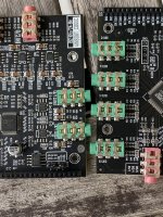
I have added headers to my board to use the additional AuxADC for level/tone controls and the MP6, and MP7 pins for a rotary encoder. I couldn't get MP9 to work. I believe it is used for one of the serial connections to the codec. I am currently using the analogue in/out for a 2 way bi amp DIY build with sub out and just about getting my head around Sigma Studio.
analogue in/out for the CS42448 codec:
View attachment 1259748 View attachment 1259749
One thing that may be a surplus action is the shorting of 2 and 3 in SIP1 in step 8
I measured my board and there is a short between 2 and 3 on the board already.
Sorry about the copy/paste.According the datasheet, we are looking for pin 34 at the DSP IC:

So following the traces from pin 34, it goes trough the SIP1 header and than R7 to (I assume) 3V3.
So this part seems to be correct.
This is important.
No action is self boot. The ADAU reading the program that is on the EEPROM.
When we want to put our own program into the EEPROM we have to make sure the ADAU does not self boot. That is achieved by shorting 1 and 3 on SIP1.
Then the ADAU can be programmed by the USBi and instructed to send program to EEPROM
@fackamato I tried the method in post #365 and it works. Seems like just the boards you gave up on.Maybe I am expecting too much
More than 0 (insert currency here) should result in a working product. But then again, these boards aren't exactly made next door. I'm going to call the boards broken for now.
Interesting, ADI support, i will try if the pass through works on my board
https://ez.analog.com/dsp/sigmadsp/f/q-a/576190/adau1452-codec-cs42448-is-not-working
https://ez.analog.com/dsp/sigmadsp/f/q-a/576190/adau1452-codec-cs42448-is-not-working
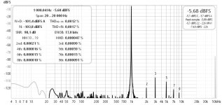
Se there are some raising noise below 4k on my setup. Guess the tiny caps and resistors on the output is to blame?
When measuring two channels as a balanced mono channel (same source, on channel inverted) the noise is way better.
Guess this combo is cheap enough to use one adau1452 /CS42448
pr speaker. So still 3 balanced inputs and 4 balanced outputs. For "mono" 4 way
When measuring two channels as a balanced mono channel (same source, on channel inverted) the noise is way better.
Guess this combo is cheap enough to use one adau1452 /CS42448
pr speaker. So still 3 balanced inputs and 4 balanced outputs. For "mono" 4 way
Attachments
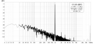
Back to the CS42448 board.
Powered it with a power bank on first measurements. Bad idea. It do not have good noise filtering on either the power bank or the CS42448 board.
Measurement with ordinary PC usb power was much better on noise in single ended mode. And excelent compared to price in balanced


Powered it with a power bank on first measurements. Bad idea. It do not have good noise filtering on either the power bank or the CS42448 board.
Measurement with ordinary PC usb power was much better on noise in single ended mode. And excelent compared to price in balanced
- Home
- Source & Line
- Digital Line Level
- low cost ADAU1452 China board...