Hi Jan,Friends, can I pick your collective brains a bit?
[...]
But for best results you really want to do synchronous FFT. The AP can do that with any input freq but a long FFT by definition will loose resolution when the source drifts. That problem is not solved by a tracking notch filter.
That is also why we have been talking here about locking an oscillator to a reference frequency, to be able to do synchronous FFTs.
To complete the tracking notch to the state that a complete project can be published I need to do quite some work. And I am a bit afraid that when I do that, it'll just sit there and have no use. That would be a waste of time and money, but I also suffer from the usual 'sunk cost syndrome'.
So I guess my question is, what would you see as a good use, if any, for a tracking notch ... ? Be honest.
Jan
Well, to be honest, I prefer my way, of course.
") That means a variable oscillator, phase locked on the dip of the (fixed and passive) notch filter. To remove harmonics from the (digital) oscillator, it should be followed by a passive band-pass filter. As for a synchronous FFT on a signal with variable frequency, you know already the answer: DiAna. I'm still working on it, as it is not that simple, mainly due to the pesky cross-talk between left and right channel of the ADC (Lynx L22 and also RTX).
That means a variable oscillator, phase locked on the dip of the (fixed and passive) notch filter. To remove harmonics from the (digital) oscillator, it should be followed by a passive band-pass filter. As for a synchronous FFT on a signal with variable frequency, you know already the answer: DiAna. I'm still working on it, as it is not that simple, mainly due to the pesky cross-talk between left and right channel of the ADC (Lynx L22 and also RTX).Cheers,
E.
All good points, and good to step back and look at it.
I can only speak for myself, and I am fascinated by trying to get as low as possible on the 1kHz (or higher, that too) harmonic spectrum.
Is it critical for designing/building very good sounding amplifiers? Probably not.
Jan
I can only speak for myself, and I am fascinated by trying to get as low as possible on the 1kHz (or higher, that too) harmonic spectrum.
Is it critical for designing/building very good sounding amplifiers? Probably not.
Jan
I'm not trying to troll here or anything bad. I'm just trying to orient myself properly. So, here goes...
What is the goal here?
Is this sort of a *very* interesting hobby of seeing just how low you can make harmonic measurements? There's obviously a lot of satisfaction in being able to push or maybe even advance the state of the art on a measurement technique. Or, pretty much anything, for that matter. That one I appreciate and get the appeal of.
Or, is this attached to some sort of scheme to improve audio performance? This is the part I'm murky on. Even if you go back to the mid 20th century, it was pretty well understood that the IMD spectrum of a non-linear device fairly well overwhelmed the simple harmonic spectrum when multiple tones were applied. Like with audio. Since the linearity of an amplifier varies with frequency - for a ton of reasons people here are well familiar with - being able to measure 1 KHz harmonic distortion down to infinity and beyond may not be all that revealing by itself.
Understanding the problem statement would certainly help me answer whether a tracking notch is useful. It's certainly way cool and an impressive design accomplishment, but I'm not sure why I'd need one.
All good points, and good to step back and look at it.
I can only speak for myself, and I am fascinated by trying to get as low as possible on the 1kHz (or higher, that too) harmonic spectrum.
Is it critical for designing/building very good sounding amplifiers? Probably not.
Jan
I agree with Jan that pursuing low distortion is fascinating in its own right.
An interesting experiment in audibility that I've often thought about but never conducted: Use any good any good THD analyzer to self-test its own 1kHz oscillator and port its monitor output to a good audio system. Would the nulled distortion output be audible in the underlying noise? I suspect not.
But that would NOT deter my continuing interest.
Last edited:
An interesting experiment in audibility that I've often thought about but never conducted: Use any good any good THD analyzer to self-test its own 1kHz oscillator and port its monitor output to a good audio system. Would the nulled distortion output be audible in the underlying noise? I suspect not.
I'll try it tomorrow! ;-)
Jan
I've started another thread that may be of interest, even though the circuitry doesn't get to the "super low distortion" discussed here:
New Lower Distortion Tri-to-Sine Shaper
New Lower Distortion Tri-to-Sine Shaper
Friends, can I pick your collective brains a bit?
I have been interspersing this thread with posts about my tracking notch filter (and thank you for not protesting that, it could have been considered a bit OT). I am not sure what to do next. The prototype has been proven to work, if the signal level doesn't get too much above 1V all harmonics are just below -140dBc, and it tracks the nominal 1kHz input at +/-3Hz. The reason for my work was to be able to use an external notch filter which tracks an external oscillator for analysis with my AP 2722. (Using an external notch before the analyzer input greatly reduces the AP analyzer self-distortion).
But for best results you really want to do synchronous FFT. The AP can do that with any input freq but a long FFT by definition will loose resolution when the source drifts. That problem is not solved by a tracking notch filter.
That is also why we have been talking here about locking an oscillator to a reference frequency, to be able to do synchronous FFTs.
To complete the tracking notch to the state that a complete project can be published I need to do quite some work. And I am a bit afraid that when I do that, it'll just sit there and have no use. That would be a waste of time and money, but I also suffer from the usual 'sunk cost syndrome'.
So I guess my question is, what would you see as a good use, if any, for a tracking notch ... ? Be honest.
Jan
Hi Jan,
Congratulations on the excellent performance you have achieved.
The simple answer to your question is that it is much better than other notch filter approaches like passive or active twin-T in virtually any way that they are used.
For use with distortion analyzers, it is understood that the analyzer performance will be improved if the signal source is synchronous with the FFT. This applies to FFT-based analyzers.
However, your tracking notch does not depend on synchronicity with traditional non-FFT-based distortion analyzers, so their starting performance can be improved many-fold with the tracking notch filter. Moreover, the residual output of the conventional THD analyzer can be further analyzed by an FFT. At this point, the FFT will not have to be synchronous to yield exceptional overall measurement system results. A simple example would be use of an upgraded HP339 THD analyzer. The tracking notch filter makes this approach much easier and better, but is not functionally different then the way we have put twin-T filters in front of distortion analyzers in the past.
The tracking notch filter is another good tool in the toolbox. I would guess, however, that the amount of use of it would be less than that of the Auto-ranger.
Cheers,
Bob
Bob, at this moment I use a passive twin-tee (I have a single-ended and a fully balanced version) for the measurements with the AP. That works very well with the external Viktor oscillator, because although that oscillator drifts slightly, the dynamic range on the analyzer A-D is still greatly reduced. Even if the signal isn't right down the notch frequency, but slightly off, it still decreases the fundamental by more than 30dB. And that is enough to get down to the noise floor.
The problem starts when I want to do say 50 seconds FFTs for ultra low residual noise (very narrow bins like 0.05Hz). That is limited by the slight oscillator drift over that long period so you get spectral leakage.
That cannot be cured by a tracking notch, only by making the oscillator frequency rock-stable, i.e. locking it to an other stable oscillator like a sound-card or the AP digital oscillator.
I don't think there are many people these days using a non-FFT spectrum analyzer, but I may be wrong.
Jan
I don't think there are many people these days using a non-FFT spectrum analyzer, but I may be wrong.
Jan
There are quite a few of us who use both.
How difficult would it be to convert your notch to a tracking bandpass filter for a digital source? If you could reduce the harmonics of a soundcard by 20-40 dB you are way down in the mud.
Then the notch fits the system better.
There are quite a few of us who use both.
How difficult would it be to convert your notch to a tracking bandpass filter for a digital source? If you could reduce the harmonics of a soundcard by 20-40 dB you are way down in the mud.
Then the notch fits the system better.
The notch is based on the Bainter filter. I don't think it has a bandpass output, so you'd need some additional circuitry. Food for thought.
Jan
There are quite a few of us who use both.
How difficult would it be to convert your notch to a tracking bandpass filter for a digital source? If you could reduce the harmonics of a soundcard by 20-40 dB you are way down in the mud.
Then the notch fits the system better.
I also use both. For FFT I use the QA401, which is a great box. For traditional, I use my own THD analyzer that I designed. I also occasionally use my analog HP3580A spectrum analyzer. It goes up to 50 kHz, so is fine for 1 kHz fundamental stuff, but almost useless for 20 kHz unless the 2nd harmonic is all you are interested in.
Cheers,
Bob
Several extremes here:
1) (primary) Boonton 1120 => Wavetek 7530A FFT plugin for a Tek scope with a Tek dual beam for waveform, full and notched.
2) Shibasoku AM70A to Siglent for waveform display. The AM70A has harmonic analysis.
3) For deeper- Victor oscillators to Shibasoku 750D to soundcard or QA401 or RTX and Diana. (lower floor)
4) For the hopeless pursuit of useless- Radiometer CLT-1 to DUT to CLT-2 (-170 dB floor for H2 of 10KHz, Yes, I have two of them).
#1 is on the bench and what I normally use since its fast and has synthesizer frequency accuracy.
Last edited:
Is there an AA (Analyzer Anonymous) discussion group ;-) ?
But I get the point.
BTW Converting a notch to a bandpass with a simple subtracting stage will not work because of the phase relationships and the phase flip at the notch frequency.
Unless someone knows a method that works?
BTW2 The AP notch can be set to track the incoming signal (setting 'Counter Track') but that doesn't help with the slow oscillator drift during very long FFTs.
Jan
Last edited:
Hi all,
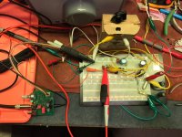
I just fired up Victors oscillator and using mikebeth's power supply schematic that
he's going to make power supply boards for Victor's oscillator. Mikey's post is #8700.
It's designed for a 16VAC walwort transformer into his board, then connected to
Victor's Osc at 35VDC.
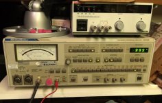
My first pass firing up the oscillator plugged in to my Shibasoku 725D came in at
a whopping -60dB, using the red RCA through Mic cable connected to the kluged
shielded Banana Jack adapter to BNC, then BNC to BNC to the 725D.
After a brief cogitation period which involved looking for some better cabling
options, making dinner for my little six year old girl, going through bins and bins
of cables and connectors...at least I found one that would work. It's the Female Banana
Jack to Male BNC connector. So I plugged RCA into black side, using the mic cable, and
plugged the male Bananas into the female bananas, and with standard good BNC cable
ran it to the trusty Shibasoku 725D. And, this time I included a ground connection from the
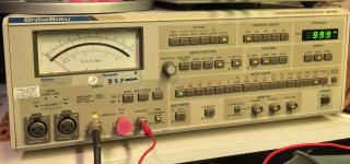
distortion analyzer Victor's ground screw. Low and behold I now have distortion down to
between -120dB and -124dB w/o a notch filter in the open air.
The lowest measurement, was with the "option" filter. Don't ask, I have no idea which
or what that filter does, there is no documentation for it.
This brings up a couple of questions I have and maybe 1Audio (Demian) or
someone familiar with the Shibasoku 725D or other meters can help with
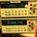
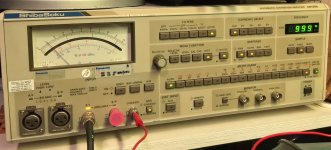
the final calculations of THD in dB or percent. My focus is on the last two images.
06.OptionOnly: THD Measured, MeterRange 0.001%(-100dB), MeterDisplay = .02% (>-20dB)
06.OptionOnly: THD Measured, MeterRange0.0003%(-110dB), MeterDisplay = 11% (-19dB) Note: Gain-10dB Selected.
for the 06.OptionOnly Reading, it should be -100dB from Range + -20dB from Meter, + -9dB of range from the -10dB Button.
or -129dB at 999Hz in open air, no shielding for Victor's Oscillator.
or from percent calculation, 0.001% x .11% = 0.00011%.
I'm thinking this is pretty good all things considered, what think y'all?
Will I gain another -20dB to -30 dB using shield in box,
and using a notch filter?
Cheers,
Here are the pics.
Post Script - When I was measuring the harmonics of automotive coils, and was looking in the area of 300kHz,
the Shibasoku 725D gave me readings of it. I was amazed, that it looked at harmonic data up to about 1MHz,
before it petered out. This machine is a lot better then it's data sheet by a large margin.
I just fired up Victors oscillator and using mikebeth's power supply schematic that
he's going to make power supply boards for Victor's oscillator. Mikey's post is #8700.
It's designed for a 16VAC walwort transformer into his board, then connected to
Victor's Osc at 35VDC.
My first pass firing up the oscillator plugged in to my Shibasoku 725D came in at
a whopping -60dB, using the red RCA through Mic cable connected to the kluged
shielded Banana Jack adapter to BNC, then BNC to BNC to the 725D.
After a brief cogitation period which involved looking for some better cabling
options, making dinner for my little six year old girl, going through bins and bins
of cables and connectors...at least I found one that would work. It's the Female Banana
Jack to Male BNC connector. So I plugged RCA into black side, using the mic cable, and
plugged the male Bananas into the female bananas, and with standard good BNC cable
ran it to the trusty Shibasoku 725D. And, this time I included a ground connection from the
distortion analyzer Victor's ground screw. Low and behold I now have distortion down to
between -120dB and -124dB w/o a notch filter in the open air.
The lowest measurement, was with the "option" filter. Don't ask, I have no idea which
or what that filter does, there is no documentation for it.
This brings up a couple of questions I have and maybe 1Audio (Demian) or
someone familiar with the Shibasoku 725D or other meters can help with
the final calculations of THD in dB or percent. My focus is on the last two images.
06.OptionOnly: THD Measured, MeterRange 0.001%(-100dB), MeterDisplay = .02% (>-20dB)
06.OptionOnly: THD Measured, MeterRange0.0003%(-110dB), MeterDisplay = 11% (-19dB) Note: Gain-10dB Selected.
for the 06.OptionOnly Reading, it should be -100dB from Range + -20dB from Meter, + -9dB of range from the -10dB Button.
or -129dB at 999Hz in open air, no shielding for Victor's Oscillator.
or from percent calculation, 0.001% x .11% = 0.00011%.
I'm thinking this is pretty good all things considered, what think y'all?
Will I gain another -20dB to -30 dB using shield in box,
and using a notch filter?
Cheers,
Here are the pics.
Post Script - When I was measuring the harmonics of automotive coils, and was looking in the area of 300kHz,
the Shibasoku 725D gave me readings of it. I was amazed, that it looked at harmonic data up to about 1MHz,
before it petered out. This machine is a lot better then it's data sheet by a large margin.
Attachments
Last edited:
Who owns Viktor's oscillator certainly knows its output voltage range.
Vic1k voltage range (unloaded, 600R output imp)
min 0.288 Vrms
max 2.782 Vrms
0.29Vrms is too much when somebody wants to measure poweramp at low powers, let's say 1W/4R. For lowering the oscillator output voltage I use voltage divider in unusual way, RCA plug with 150R resitor inside. Then the modified range is:
Vic1k 1:5, output imp 120R
min 0.056 Vrms
max 0.556 Vrms
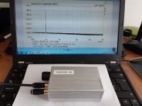
The performance is still excellent:
H1: -10dBV (0.31 Vrms)
H2: -157dBV/noise (passive notch, no correction on graph)
H3: -159dBV/noise (passive notch, no correction on graph)
Vic1k voltage range (unloaded, 600R output imp)
min 0.288 Vrms
max 2.782 Vrms
0.29Vrms is too much when somebody wants to measure poweramp at low powers, let's say 1W/4R. For lowering the oscillator output voltage I use voltage divider in unusual way, RCA plug with 150R resitor inside. Then the modified range is:
Vic1k 1:5, output imp 120R
min 0.056 Vrms
max 0.556 Vrms
The performance is still excellent:
H1: -10dBV (0.31 Vrms)
H2: -157dBV/noise (passive notch, no correction on graph)
H3: -159dBV/noise (passive notch, no correction on graph)
Attachments
What FFT length was the measurement? Arta's max is 128k. At 48kHz that means 0.37Hz bin, 19 averages take 52 secs. By how much could have the frequency moved in 52 secs? I think it is important to consider the frequency drift in this measurement. Maybe it was way less, but maybe it was in that range, I really do not know. Thanks.
What FFT length was the measurement? Arta's max is 128k. At 48kHz that means 0.37Hz bin, 19 averages take 52 secs. By how much could have the frequency moved in 52 secs? I think it is important to consider the frequency drift in this measurement. Maybe it was way less, but maybe it was in that range, I really do not know. Thanks.
Very little, if you warm it up for > 1hr:
https://www.diyaudio.com/forums/equ...n-audio-range-oscillator-839.html#post6110003
Jan
- Home
- Design & Build
- Equipment & Tools
- Low-distortion Audio-range Oscillator