CeeVee. I felt bad for contributing to this problem by asking for a schematic....I don't have that Andrew...just a PDF with the project....if the moderators think it's best please remove the schematics.
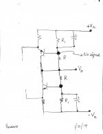
I recall posting schematic like the attached in a dialogue with lhquam in a Pass Labs thread; which escapes me now. This schematic shows a simple approach to DC servo this unique and popular preamp. Note the following:
- An electrolytic capacitor is added across R1. Thus, the bases of the cascode bjts are grounded; meaning no AC signal appears at these junctions to alter the design AC gain [Vo] of the bjts operating in the common base configuration.
- The middle junction of the resistor ladder [R1-R*R-R1] biasing the folded cascode bjts is connected to Vo. Thus Zo of the amp is R/2.
- When the DC voltage at Vo becomes or drifts positive from its initial state, the NPN turns more on and the PNP turns more off. The reverse happens when the DC voltage at the output goes negative. This is negative feedback which acts to restore the initial quiescent DC voltage which initially maybe 0VDC [or close to it] by careful design.
- The bjts operate as undisturbed folded cascodes for the AC signal and as inverters for an emerging DC offset component.
Attachments
Thanks; will try it.For a schematic, just type the name of the file in google images. (mind level Zero, as the current generation)
Indra1. The title of your circuit may easily be LSK Preamp meets diyF4. But your diyF4 is truly bare bones; ...
Hi Antoinel,
I was messing around with Juma's circuits at post #66 of this thread and http://www.diyaudio.com/forums/pass-labs/162042-f5-meets-buzquito.html#post2097690. My change to the published circuits was only the 150 ohm R23 and R24 which Juma replaced by 120 ohm Resistor in series with 200 ohm Pot at post # 118 of this thread.
You can absolutely use Vertical MOSFET F4-style or complementary Bipolar as output provided adequate biasing scheme to prevent thermal runaway is met, and yes, shunt type voltage bias such as thermally coupled Vgs or Vbe multiplier is preferred.
However, the use Lateral MOSFET with the intrinsic negative tempco lends itself readily for very simple and stable resistor biasing scheme, even without source degeneration as on post #118 of this thread. And due to bootstraping effect of source follower configuration, I was hoping that 8ma input jfet bias will be enough to drive the input capacitances of the Latfet. If 8ma is not enough, I suspect that high frequency distortion will somehow be noticeable and plan to parallel the Input Jfets to have bias at about 15-17 ma. However, It seems that Juma prefers to drive the Latfet with Bjt which I may have to use if the parallel input jfet is still unsatisfactory. I'm still out of town, so my build will still have to wait.

LSK Preamp can also meet complementary SITs
Hello Indra1. The output stage of the SONY VFET amp [CES demo] operates in the common drain configuration per Mr. Pass. Your schematic which is attendant to your post #76 can be conceptually modified as follows to potentially be [aka a wild but an educated guess] a simplified concept of that SONY VFET.Hi Juma,
Thanks a lot for the great bjt cascode version implementation of the PASS BAF2013 LSK preamp.
I came up with an idea and hope that you do not mind my using photoshop to merge several of your schematics of LSK Preamp, F5 meets Buzquito and addition of 2x150R at (R23 & R24) for an integrated with no global NFB. Any comments or suggestions for a build with sk/sj pair at idss about 10ma?
Thanks in advance.
- Substitute the N-ch MOSFETs with N-SITs
- The new gate drive to N-SITs is the junction of R24 and the collector of Q4. This gate voltage is negative wrt ground.
- Substitute the P-ch MOSFETs with P-SITs
- The new gate drive to P-SITs is the junction of R23 and the collector of Q3. This gate voltage is positive wrt ground.
- Augment the current flowing through R23 and R24 by connecting 2 suitable and equal resistors to the + and - voltage rails. This will increase the voltage bias spread to the SITs; with a minimal impact on the original design of the front end.
Those are small laterals and there is no direct replacement for them outside of the same family (2sj76,77,78,79/2sk213,214,215,216). You could use some nice verticals like 2sk2013/2sj313 but the circuit had to be redesigned to deploy them (different Vgs/Id, different tempco, etc...).
I've looked around, nothing but counterfeits out there.
I love the idea of a servo. Can the LSK be adapted?
Hello Indra1. The output stage of the SONY VFET amp [CES demo] operates in the common drain configuration per Mr. Pass. Your schematic which is attendant to your post #76 can be conceptually modified as follows to potentially be [aka a wild but an educated guess] a simplified concept of that SONY VFET. ...
HI Antoinel,
Please refine your idea as it has a fundamental catastrophic failure mode on voltages close to clipping similar to J. Hiraga design. Kindly read Ilimzn explanation at http://www.diyaudio.com/forums/solid-state/241272-what-do-sony-v-fets-8.html#post3643111..
Regards,
Indrawan
... I love the idea of a servo. Can the LSK be adapted?
Sure, but with some thermo-coupling and adjusting we can do without it.
Sure, but with some thermo-coupling and adjusting we can do without it.
That is exactly the approach Patrick ( EUVL ) has taken in his F5X Preamp as well
 .
.Thank you Indra1 for your coaching and suggestion. I am glad to see that you are in touch with this interesting subject. Clearly, I need more education by using the suggested thread plus the additional schematics of Juma and Mos57.HI Antoinel,
Please refine your idea as it has a fundamental catastrophic failure mode on voltages close to clipping similar to J. Hiraga design. Kindly read Ilimzn explanation at http://www.diyaudio.com/forums/solid-state/241272-what-do-sony-v-fets-8.html#post3643111..
Regards,
Indrawan
Best regards
Anton
Hi Juma;
I plan to build these using Parasimixs' boards and am looking forward tot he results.
I have a question about the power transformer. Assuming an 18V winding as shown in the post 66 schematic; I don't see how we can get 33V or enough voltage headroom for the 24V regulator. ((18 X sqrt(2))/1.11)-1.4) yields about 21.5V. Even if the transformer had say 20% regulation and we were loading it lightly we'd only hit 25V at best. What am I missing?
Thanks
Matt
I see it...voltage doublers!
Last edited:
Hi Juma;
I plan to build these using Parasimixs' boards and am looking forward tot he results.
I have a question about the power transformer. Assuming an 18V winding as shown in the post 66 schematic; I don't see how we can get 33V or enough voltage headroom for the 24V regulator. ((18 X sqrt(2))/1.11)-1.4) yields about 21.5V. Even if the transformer had say 20% regulation and we were loading it lightly we'd only hit 25V at best. What am I missing?
Thanks
Matt
I see it...voltage doublers!
And not even that...
just AC coupled into the rectifiers. Never seen that before. Good for low currents I guess. Cool.AC coupled using polar electrolytics between TX and rectifiersAnd not even that...
I guess I also have to study a bit to understand how one can get away with this.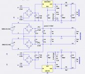
Yes (to post 335); that's what I was saying in the next post (333). I think my notion of a voltage doubler was erroneous.
I have never seen this before. I guess as long as the caps can tolerate the max voltage and current it should work. I'm not sure about grounding the centre tap of the transformer.
I have never seen this before. I guess as long as the caps can tolerate the max voltage and current it should work. I'm not sure about grounding the centre tap of the transformer.
Last edited:
Ok I think I get it.
The two 18V secondaries are in series with the centre grounded.
The charged caps keeps both half of the full wave bridge conducting contemporarily (therefore doubling the voltage?)
The rectifier bridges keeps the electrolytics polarised correctly as current only flows in one direction.
Possibly stupid question: what is the advantage of this over simply getting a dual secondary 36V transformer and using a "normal" configuration with smoothing caps after the rectifiers? No rectifier on/of noise?
Last edited:
Possibly stupid question: what is the advantage of this over simply getting a dual secondary 36V transformer and using a "normal" configuration with smoothing caps after the rectifiers? No rectifier on/of noise?
Not stupid at all. The only stupid questions are the ones not asked.
This configuration gives 2 voltages off one transformer. The 'normal' voltage is the one that requires more current, hence the PSU being made for that voltage, and the higher doubled supply is easy to make from the LV supply.
IF you were to make a higher-volt supply and regulate down to the lower voltage or use dropping resistors, it would be very inefficient.
- Home
- Amplifiers
- Pass Labs
- LSK pre - BAF 2013