X,
PCBs are looking very nice - another superb effort by JP!
UMS heat-sink compatibility, low parts count, and spaced out layout of the PCB should make it very easy for DIYers to build this amp.
Many of the gang already have +/-24 V power supplies - what sort of output power can they expect from that?
PCBs are looking very nice - another superb effort by JP!
UMS heat-sink compatibility, low parts count, and spaced out layout of the PCB should make it very easy for DIYers to build this amp.
Many of the gang already have +/-24 V power supplies - what sort of output power can they expect from that?
Great question, Zman. I just ran the LTSpice simulation for 24v single rail supply and I was able to get 27.5w rms with 0.08%THD. At 30wrms into 8ohm, the THD is 0.5%. If that is acceptable as an upper limit, then I would say that you could get 30w, but I think it is closer to 28w for 24v rail.
Keep in mind that you will need a preamp that can drive 44Vpp cleanly in order to achieve the 28w though.
Keep in mind that you will need a preamp that can drive 44Vpp cleanly in order to achieve the 28w though.
Last edited:
Hi Tungsten,
That’s great news - because there is already an M2X format WBA18 preamp module that can fit into the LuFo amp main board. One just needs to provide it +/-28v. Which could be done using the new double mezzanine DCDC with revised resistor programming values to achieve the lower voltages. Or use an external PSU (could utilize the existing secondaries from main transformer). Thanks for pointing that out. In fact, my memory is now jogged and I recall running the M2X format WBA18 at +/-30v:
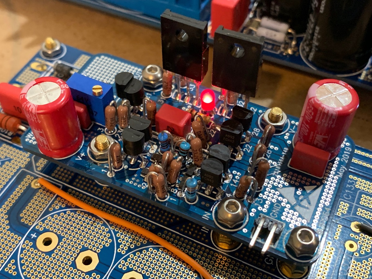
Here was FFT with 29dB gain:
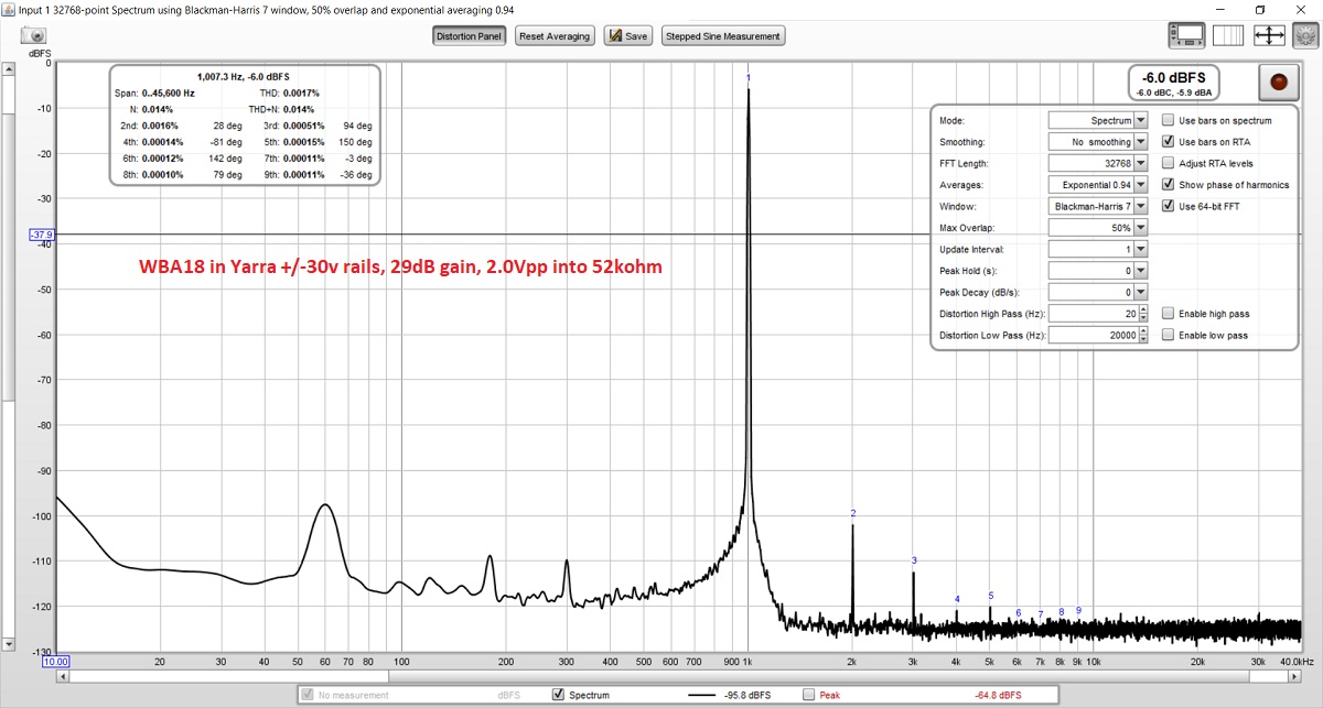
On my implementation I recall it ran rather hot - it could probably use a bit of a lower bias current if only driving preamp line level loads vs headphone loads.
Or one could use the WBA18 externally, which many people have built already from the giveaway.
That’s great news - because there is already an M2X format WBA18 preamp module that can fit into the LuFo amp main board. One just needs to provide it +/-28v. Which could be done using the new double mezzanine DCDC with revised resistor programming values to achieve the lower voltages. Or use an external PSU (could utilize the existing secondaries from main transformer). Thanks for pointing that out. In fact, my memory is now jogged and I recall running the M2X format WBA18 at +/-30v:
Here was FFT with 29dB gain:
On my implementation I recall it ran rather hot - it could probably use a bit of a lower bias current if only driving preamp line level loads vs headphone loads.
Or one could use the WBA18 externally, which many people have built already from the giveaway.
Last edited:
Hi Anand,
As this amp was discussed openly here in Pass Forum, I will make the Gerbers freely available for anyone wishing to order their own boards or to organize a GB. We will need to verify that the design works first before I release the Gerbers for public consumption. Unfortunately, I don’t have time to organize GBs anymore.
I have a few spare boards if anyone wants to be a beta tester along with Vunce and myself.
Good to hear,does that include the preamp module?I will make the Gerbers freely available for anyone wishing to order their own boards or to organize a GB.
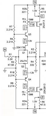
It is often interesting to look at the development history of the designs that we use. Here is a schematic of the original 'purple' BA2018 line stage, annotated by 6L6. This version originally used smaller output devices before being modified for use as a headphone amp. In this form, it was Ok to run at +/– 28V, perhaps with some care to keeping the outputs from getting too hot. I think some small tweaks to the output bias could make it safe to run at +/– 30V. Perhaps increasing the emitter degen resistors from 27Ω to 30Ω? There are small clip-on TO-92 heatsinks that could be used as well.
Edited to add:
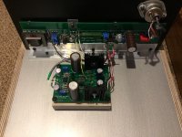
I actually have a pair of the Yara/M2x Wayne's BA18 Preamplifier PCBs. Since the WBA18 is known to have a good PSRR, I feel pretty confident that it would work with the switching PSU mezzanine board.
Edited to add:
I actually have a pair of the Yara/M2x Wayne's BA18 Preamplifier PCBs. Since the WBA18 is known to have a good PSRR, I feel pretty confident that it would work with the switching PSU mezzanine board.
Attachments
Last edited:
I could be proven wrong but did not see enough interest in SMT-centric boards here.Good to hear,does that include the preamp module?
Is there a publicly available BA3 preamp PCB with cascoded input JFETs that can be run at + / - 30+ v? I suppose one could use the DIY store VFET PCBs.
Indeed!
Best,
Anand.
Attachments
Indeed!
Best,
Anand.
That is a schematic. My ask was a PCB.

That is a schematic. My ask was a PCB.
Sorry. I was just nodding in agreement when I realized the front end of the diyaudio VFET was a BA-3 lookalike!
Best,
Anand.
No, but here are the files. The rev 3 schematic is just updated values.
It has a few modifications but can be used for the original circuit as well.
Sweet. Nice work. Much appreciated.
- Home
- Amplifiers
- Pass Labs
- LuFo Amp - 39w SE Class A from 28v Rail