

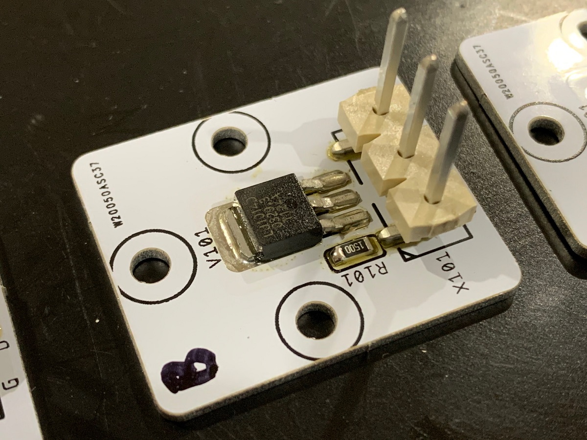
I made a 5 part video on how to install the LU1014D’s onto these metal substrate boards here:
https://www.diyaudio.com/community/threads/assembling-the-lu1014d-ims-to-247-adapter.373273/
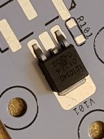
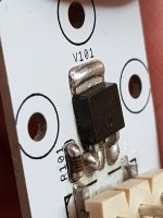
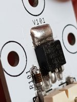
Not sure what Ihquam’s method is, but it looks like you did not get full melt and could be issue with thermal bonding between back of the JFET and the IMS board. 15W of power needs to flow through that solder pad.
Use a small hot plate/skillet and solder paste - that’s the easiest way to do it. I don’t think any soldering iron can provide enough heat to fully melt and wet the parts to fully flow the solder under the JFET.
https://www.diyaudio.com/community/threads/assembling-the-lu1014d-ims-to-247-adapter.373273/
Not sure what Ihquam’s method is, but it looks like you did not get full melt and could be issue with thermal bonding between back of the JFET and the IMS board. 15W of power needs to flow through that solder pad.
Use a small hot plate/skillet and solder paste - that’s the easiest way to do it. I don’t think any soldering iron can provide enough heat to fully melt and wet the parts to fully flow the solder under the JFET.
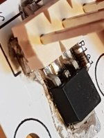
Might be fine. What I look for is the concave interface of the solder against the substrate and part to show it fully wetted and is a thin layer. Your part forms a convex interface which might indicate the wetting was not complete and you may have a cold solder joint. Although it might just be that there is excessive solder so it forms a convex bulge. It may have higher thermal resistance. Did you use solder paste and a hot plate or wire solder and an iron?

Yes, it depends on how much heat you expect to transfer. I have done this for a headphone amp with a few watts of dissipation. On the LuFo it’s about 12W I think so kind of on the edge there. The metal substrate TO-247 adapters are really the best and easiest to use solution.
I am listening to my hybrid Lufo and it sounds fine. The front end is 6e5p.Now to the problem ,there is a beeping sound through the speakers about 1khz I can hear it if I am close to the speakers.
I am blaiming the switch mode supply...
How many VA should a toroid be that driver both channels?

I am blaiming the switch mode supply...
How many VA should a toroid be that driver both channels?
- Home
- Amplifiers
- Pass Labs
- LuFo Amp - 39w SE Class A from 28v Rail