Common base is the configuration of choice in many very high frequency applications such as RF amplifiers as it features moderate to high voltage gain (but no current gain). The output impedance is very high though.
Your circuit will work although transistor choice is important. I would have thought a device specified for RF use would be more appropriate tbh. I don't what modern devices are available but I've worked with the older BF and BFY devices which had transition frequencies in the GHz region and above and were used as RF amplifiers in UHF tuners and the like.
The circuit has around -/+450mv output capability and could probably benefit from more optimal biasing (you need to alter the base voltage). Doing that gets you closer to -/+ 1 volt swing.
This is the output for 1mv peak input. Input frequency lower than your requirement to suit common transistors.
Attachments
Common base is the configuration of choice in many very high frequency applications such as RF amplifiers as it features moderate to high voltage gain (but no current gain). The output impedance is very high though.
Thanks for helping out. I'm trying to use Common Base to boost the Q of the resonant circuit, at the moment I can inject a 10uA current into the resonant circuit and get three volts p-p out, that's a lot of gain! Also the very low Emitter virtual resistance boosts Q.
My problem is bias, I can only do this by putting a voltage source at the Base, if I try same with bias resistors and decoupling capacitor circuit does not work.
I know that Common Base provides non-inverting voltage gain with zero phase shift, I'm wondering how to control the very low virtual Base resistance and if it can be made negative resistance?
Last edited:
Common base is used all the time, a cascode is a common-emitter into a common-base. Common-base avoids the Miller effect, and it prevents voltage swing on the common-emitter (avoiding Miller effect).
That's a very specific application then, following another transistor. I'm thinking about front end applications and not just RF.
Can you put up a typical circuit diagram showing Common Base? I have looked for many and conclude that many are not configured properly.
You should add a 50R resistance in serial with V3, that s the typical impedance for antennas or RF circuits,Common base is the configuration of choice in many very high frequency applications such as RF amplifiers as it features moderate to high voltage gain (but no current gain). The output impedance is very high though.
Your circuit will work although transistor choice is important. I would have thought a device specified for RF use would be more appropriate tbh. I don't what modern devices are available but I've worked with the older BF and BFY devices which had transition frequencies in the GHz region and above and were used as RF amplifiers in UHF tuners and the like.
The circuit has around -/+450mv output capability and could probably benefit from more optimal biasing (you need to alter the base voltage). Doing that gets you closer to -/+ 1 volt swing.
This is the output for 1mv peak input. Input frequency lower than your requirement to suit common transistors.
View attachment 1261255
otherwise the sim will be truncated.
You should add a 50R resistance in serial with V3, that s the typical impedance for antennas or RF circuits,
otherwise the sim will be truncated.
") Thanks.
Thanks.(I'd like to know what frequency he is dealing with here... kHz or MHz)
I'll post this if anyone wants to carry on. The thick trace is caused by ringing but we are at 17.2kHz here:
Attachments
The thick trace is caused by ringing but we are at 17.2kHz here:
Don't know why you get ringing.
With vb at +2V I can increase R5 the collector resistor to 10K, with vb at 0V I can't increase R5.
Yes agreed, the circuit on the left has no inductor so LTSpice is assuming a small inductance and creating a much higher frequency and without Q at a small amplitude.@Mooly It looks like your graph is showing the sum of the outputs of the voltage driven and current driven circuits. Why have the Vout's shorted like that?
My design frequency is 17.2 kHz.
Oops should be 17200 Hz thanks.In post #1 you show 17200 kHz
You have vb=-2V, so you have more headroom than vb=0v for DC drop across RL. That may explain why the R divider with AC shunt did not work well, if you biased at +2V.Don't know why you get ringing.
With vb at +2V I can increase R5 the collector resistor to 10K, with vb at 0V I can't increase R5.
View attachment 1261343
A cascode is common-emitter driving common-base by definition!! Front ends of amps are often folded cascode.That's a very specific application then, following another transistor. I'm thinking about front end applications and not just RF.
A differential pair with one input grounded is emitter-follower driving common-base, although that's usually only used at RF.
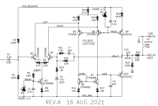
Since we're here on the diyAudio Forums, I thought it might be useful to show an example a common base configuration that's used fairly often in audio circuits. It's called "folded cascode" , see attachment below.Magical Common Base configuration, why so little used?
In a folded cascode, a common emitter transistor of polarity (A) drives a common base transistor of polarity (not-A). In this example, NPN common emitter transistor Q2 drives PNP common base transistor Q5. {similary NPN Q4 drives PNP common base Q8}
The circuit snippet below is part of a product that is offered for sale in the diyAudio Store: "Dreadnought". It's a field-swappable front end card for audio power amplifiers "VFET lottery" and "Ship Of Theseus".
_
Attachments
You have vb=-2V, so you have more headroom than vb=0v for DC drop across RL. That may explain why the R divider with AC shunt did not work well, if you biased at +2V.
Yes thanks again the bias was -2V not 2V. Still with -2V I can replace the voltage source with a bias network and works ok as before.
Attachments
Since we're here on the diyAudio Forums, I thought it might be useful to show an example a common base configuration that's used fairly often in audio circuits. It's called "folded cascode" , see attachment below.
In a folded cascode, a common emitter transistor of polarity (A) drives a common base transistor of polarity (not-A). In this example, NPN common emitter transistor Q2 drives PNP common base transistor Q5. {similary NPN Q4 drives PNP common base Q8}
The circuit snippet below is part of a product that is offered for sale in the diyAudio Store: "Dreadnought". It's a field-swappable front end card for audio power amplifiers "VFET lottery" and "Ship Of Theseus".
_
That's a very specific application then, following another transistor. I'm thinking about front end applications using Common Base at audio frequencies.
Can you put up a typical circuit diagram showing Common Base front end?
In my application above the Common Base shows amazing gain but is helped by the Q of the resonant circuit.
- Home
- Amplifiers
- Solid State
- Magical Common Base configuration, why so little used?