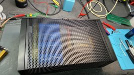
Probably a bit of a silly question, but I'm curious to know other's experience. I'm currently doing amp guts tetris and looking at different layouts, and one of the positions that would work will put the mains transformer pretty close to one of the amp boards, as pictured.
This is way too close, right? Will the copper shielded transformer help at all? What if I put another layer of copper shield between them?

This is way too close, right? Will the copper shielded transformer help at all? What if I put another layer of copper shield between them?
I don't think it's too close. More important is to consider the radiation pattern of the magnetic field. For your transformer, the magnetic field has lobes that extend out from the exposed winding sides, so it's best to keep them pointed away from low level signals. So, the PCB that you're holding would be subjected to that magnetic field.
Another thing to be aware of is the potential of wires to act as antennae which will pick up noise. Twisting paired wires (signal and return) will reduce loop areas and their ability to pick up and / or transmit noise. Something to consider when laying out actual circuits. Schematics do not necessarily depict the best wiring layouts, as they are drawn for clarity, not to minimize current loop areas.
Another thing to be aware of is the potential of wires to act as antennae which will pick up noise. Twisting paired wires (signal and return) will reduce loop areas and their ability to pick up and / or transmit noise. Something to consider when laying out actual circuits. Schematics do not necessarily depict the best wiring layouts, as they are drawn for clarity, not to minimize current loop areas.

Is there any reason why you cannot switch the positions of the transformer (xfmr) and the capacitor bank to give you some isolation distance from the transformer's stray field? The copper around the xfmr does limit stray field spread but doesn't entirely eliminate it. Adding additional copper may incrementally help, not not nearly as well as just getting some distance between the circuit and the xfmr.
So it might be okay then? I'm going to have to try it.I don't think it's too close. More important is to consider the radiation pattern of the magnetic field.
I could, but not in this chassis that I'm working on. I was planning on using only half of these capacitors, but I have a case full of these 15V ones, so I've got them in series. Here's how it'll have to sit in this chassis.Is there any reason why you cannot switch the positions of the transformer (xfmr) and the capacitor bank
So, I can flip it, it's just going to be near the other channel instead.
Attachments
You can rotate the transformer when the circuit is up and running and find the orientation of lowest noise. Best to power down before adjusting, of course.
Not silly at all. This can be very challenging depending on the circuit you have.Probably a bit of a silly question
Specially low signal pre-amps. Once I built a pre-amp for a ribbon mic (micro volts) and the only way to locate the transformer was outside the box.
Electromagnetic shielding is not easy. Modeling all the interactions is too complicate.
For power amps, in general, it's less critical, since you deal with higher levels (line level and up)
The suggestion made by pinholer is good - I made a lot of this exercise when using small enclosures - rotating the transformer, moving it around with the circuit on. Once found the good position, I fixed it. You can also move the PCB trying to find a better place if noise is present.
A ground plane right below the PCB can also help.
They do, actually. They're made like that.like they have some rather large dents.
Dynaco built a steel box inside the chassis of the PAS2/3 preamp to keep the steel encased transformer humming into 50x gain preamp circuits. They sold tens of thousands of them.Probably a bit of a silly question, but I'm curious to know other's experience. I'm currently doing amp guts tetris and looking at different layouts, and one of the positions that would work will put the mains transformer pretty close to one of the amp boards, as pictured.
This is way too close, right? Will the copper shielded transformer help at all? What if I put another layer of copper shield between them?
Fairly successful PA builder Peavey copper bound most transformers. They still encased the IEC inlet, surge elimination parts, and the main transfomer behind steel bulkheads, to protect the inlet gain stages from hum. Examples PV-1.3k, MMA875t that I own. Filter capacitors are between the AC bulkhead and the driver boards.
As a counter example, the Herald (also Olson) RA-88a disco mixer had the steel encased AC transformer 1 cm from the high gain 50x magnetic phono circuit. Also the AC power switch. I bought it for $15 at the flea market and it hummed and hissed about 40 db down from phono signal. Moving the +- op amp supply to a wall transformer, installing dual pi hum filtration, and changing the hissy 4558 op amps to 33078, made it a product that competes with the $300 RIAA preamps for sale these days.
Last edited:
Philips did this with electrolytic caps for enhanced rigidity and industrial use in vibration rich environments (AFAIK). Sometimes also a better heat transfer is mentioned which I doubt. Very old stuff, they don't produce caps anymore since 1999. The ones on the picture are made in 1997 so 28 years old. After Philips they were made by a spin off called BC Components and these were eventually sold to Vishay.the two on the left side look like they have some rather large dents.
I forgot how the innards are with these but there likely is a plastic bracket inside.
Last edited:
Oh yeah, they're pretty old. They all seem to test okay, so, I'm usin em!The ones on the picture are made in 1997 so 28 years old.
One thing to be careful about when hooking large 'lytics in series is to be sure that the voltage applied across the series pair divides equally between the two capacitors. That might not happen for two reasons. One is that on power up, if one of the caps has a bit more capacitance, the smaller cap will fill up faster and could suffer an over voltage condition. The two caps should be reasonably close in C to each other to prevent that problem. The other problem that can happen would be caused by DC leakage current through the capacitors. If one leaks a bit more than the other, then the lower leakage cap will eventually have a higher voltage across it over time, and the voltage could exceed the caps working voltage spec. Best cure for that is to place equal valued resistors across each cap so that maybe a milliamp or so of current is drawn by each resistor. That will swamp out the leakage current differences between the caps and assure equal DC voltage division across them.So it might be okay then? I'm going to have to try it.
I could, but not in this chassis that I'm working on. I was planning on using only half of these capacitors, but I have a case full of these 15V ones, so I've got them in series. Here's how it'll have to sit in this chassis.
So, I can flip it, it's just going to be near the other channel instead.
I had considered doing that, I just got done adding some bleeder resistors, but I'll have a hunt around in the parts and see what I've got. I've been a little anxious about having them in series, so if that helps I'm all for it.
I found some 1% 2.2k 1/4, with the voltages I'm expecting, it should draw about 0.6mA. Hopefully that does the trick! Just happened to have 8 of them.If one leaks a bit more than the other, then the lower leakage cap will eventually have a higher voltage across it over time, and the voltage could exceed the caps working voltage spec. Best cure for that is to place equal valued resistors across each cap so that maybe a milliamp or so of current is drawn by each resistor.
Thanks. I was not aware of that case style.They do, actually. They're made like that.View attachment 1441931
Might want to go with a bit higher wattage rating, maybe 1/2 to 1 watt. 1/4 watt is a bit skimpy if there is a temporary voltage spike for some reason. It that's not a concern, then I see no problem with e 1/4 watt ones.I found some 1% 2.2k 1/4, with the voltages I'm expecting, it should draw about 0.6mA. Hopefully that does the trick! Just happened to have 8 of them.
Place a bleeder across each of the two series connected caps, rather than one across the whole pair. That way, you get the DC voltage equalization along with the bleeder function.I had considered doing that, I just got done adding some bleeder resistors, but I'll have a hunt around in the parts and see what I've got. I've been a little anxious about having them in series, so if that helps I'm all for it.
I have both on that board, but I've actually found a much better capacitor solution, lol.Place a bleeder across each of the two series connected caps, rather than one across the whole pair. That way, you get the DC voltage equalization along with the bleeder function.
Attachments

- Home
- Amplifiers
- Solid State
- Mains transformer spacing from amplifier circuits...How close is too close?