A good friend came by my house the other day with his custom made 9023-based DAC. We tried 2 sets of LPF caps of almost identical values, they both gave pretty different results in the treble department. Perhaps you should explore that area after all..
Dimdim,
I agree that the caps there will make a difference. For example, in my Soekris 1021 implementations, I replaced the LPF ceramic cap with SMD PPS film caps to good results.
BUT the Evox Rifa Polypropylene is IMHO a very good choice for this location (better than the mylar caps Sony put in the $2,000+ HAP Z1-ES! Those got changed out quickly!). The other type I'd generally use there is the Wima line of polyprops that are about the same size.
I MIGHT try a polystyrene cap there (which should be a bit better, but 5x-10x more expensive!). I won't try a Teflon cap there, putting 2 caps that are worth more than the DAC even after my mods is just not good use of resources, IMHO.
Having said that, what I heard last night suggests that while the resistor was likely a bottleneck, the capacitor is not so much.
What caps were you trying in the LPF locations?
Greg in Mississippi
"soften a little bit the result"
I'd call it "smears...."
That's what parts in the signal path usually do.
Instead of introducing parts that cover issues up, I'd rather try to find the source of
my/your issues. Are u still running through the el cheapo jacks/plugs?
And I do also think that one needs to have a closer look at the amp/dac interaction.
You can't just look at the dac output standalone.
The ESS datasheets I have are the least informative of any I've seen. They do not contain the typical sampling frequency over clock frequency chart that ALL other audio DAC datasheets I've seen show.
That said, I suspect a 49.1520 mHz clock will support 384 on the ES9023 in sync mode. That DOES work with the ES9018 (Barrows does it that way) and I believe the ES9023 and ES9018 use the same oversampling and ASRC engines. 24.5760 MHz MIGHT work, but I doubt it.
Of course, you likely have a 24/22 Kali like the rest of us!
IF you try sync-mode and IF you can get it to work at 384, that MIGHT sound even better as it would minimize the filtering performed in the chip (though you can't turn it off via I2C options like you can on the ES9016 and ES9018).
Greg in Mississippi
Nope. I have the fast clocks on the Kali . My Sabre 9023 .pdf states the frequencies
up to 192kHz fs only.
To get 384 to work 128fs MCLK would be required as minimum I guess. This means 49.152 MHz would be required. It might work. If is working satisfactory is a different issue.
"soften a little bit the result"
I'd call it "smears...."
That's what parts in the signal path usually do.
Instead of introducing parts that cover issues up, I'd rather try to find the source of my/your issues.
When I listened last night, that is DEFINITELY NOT what I heard. Compared to the 2.2Rs that were there, I heard more detail along with a lowering of the emphasis in the highs. And NO smearing!
I think Vasilis explained his design choice well. As we improve the power situation inside the Pi, we may need to revisit this, but right now it was an across the board improvement with a reduction of smears. Feel free to come on by to listen... I'll send you directions if you want.
Are u still running through the el cheapo jacks/plugs?
Yup. You got a problem with that?
I don't, I was quite happy with what I heard and hope to confirm that tonight.I have said I'll try better jacks and I will at some point. But that is a low priority at this time.
Tell you what, you get 2 Uptone Audio LPS-1s to power your Kali and MBLS the way I have and remove the power supply bottleneck you have... and I'll go and solder in some better jacks right away!
And I do also think that one needs to have a closer look at the amp/dac interaction. You can't just look at the dac output standalone.
I have standardized on what I believe is a very transparent yet sufficiently flexible setup for my systems... I have a number of passive attenuators with a 1m-1.5m length of MIT Shotgun MI-330 hard-soldered into the input side of the attenuator with a hard-soldered short (22cm-25cm) length of MIT hookup wire to the plugs to the amps. ALL input plugs are either Eichmann bullets or good XLRs (for balance inputs). ALL output plugs are good XLRs (all of my amps are wired with XLR inputs, balanced or single-ended). The attenuators include:
- two broadcast quality stepped attenuator in shunt configurations, one single-ended, one balanced.
- a TX-102 again with a broadcast quality stepped switch.
- a Silk Autoformer again with a broadcast quality stepped switch.
All of these attenuators are very good, with the stepped single ended and TX-102 at the top.
I swap plugs to change inputs between my various computer-fed DACs, CD/DVD players, and phono setups. And amps too but they don't change much.
Yup, it is inconvenient. But removing the extra connectors and switches and active circuits in a regular preamp along with making sure I have very short connections after my attenuators to my amps AND that all of my amps have a high (100K) input impedance makes this work very well and be MUCH more transparent than anything I've tried EXCEPT a direction, short connection.
This is miles above 98% of the setups out there. Yup, you can get better with a short length of hard-soldered wire, but I have no plans to do that... this is about as hair-shirt as I will go.
Again, I am VERY happy with the results. And again, you are welcome to come by to listen, I bet you'd agree.
Greg in Mississippi
Your amp-link description sounds like pure horror to me.
I dropped my TX-102 and other stuff years back.
You leave a lot on the street there.
As I said, soldered 3 inches straight to an amp board is a different world.
It's still not as "clean" as a full digital amp though. To me these fd amps are cleanest. Nothing can beat that.
However. These full digital amps usually have other issues.
I need to get me two 10Rs and a 130R to introduce the 3.6V mod. Some comments
I read say the 3.3V related clipping is awful at down rather low levels (-30%) ?? I need to take some measurements myself.
The Subbu thread folks also seem to prefer 3.6V. Hmmh.
Vasilis is saying he prefers 3.3V, still.
I'm also confused about type of caps and values used on e.g. NEG.
One of the quite crucial pins as it seems.
There are people saying, don't go above 2.2uf others like you pump it up large scale.
And as it seems Sabre wants to see a balanced value to AVCC. Going 570uf on AVCC
and leaving NEG at 1uf might not be good idea either.
Unfortunately I haven't seen any common implementation/mod strategy around this DAC chip. That's a pity.
PS:
If you pay the flight and Trump lets me still in, I'll come by.
And. No. I won't ever buy these overpriced low current supercap supplies.
I compared my stuff to supercap supplies earlier. The people in the room couldn't hear
much of a difference.
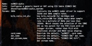
On the subject of MCLK & ESS9023...
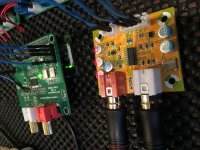
I looked around for the most stripped down & fairly common Sabre board and bought this one for 9 bucks... to experiment with i2s from raw pi/D+PRO/Digi+PRO/Kali192/kali384 etc... and to have a saber chip laying around.
Could you guys take a quick look to see how to enable external MCLK on this one... maybe remove the 100R resistor? Its a teradac 2.1, no documentation.
Connecting MCLK as is just mutes the output.
Edit: tried harder to get to their site, it finally responded: http://www.teradak.com/products/84.html Still a little vague & bad english...
Thanks!
Attachments
Last edited:
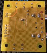
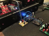
Scott,
First confirm that the right-most resistor in the 75R resistor array connects to both the MCLK pin on the header on one side AND to pin 13 on the ES9023 on the other side (fourth from the top right as shown in the picture).
If so, I agree with Dimdim.
OTOH, this is one of those situations where how well it works is HIGHLY dependent on how it is connected. Shorter is better. Note in the picture I posted of EUVL's ES9022 board that the output of the clock on that board is one 0604 SMD resistor away from pin 13.
You'd do best to keep those connecting wires to 1" or shorter.
Oh, and I just realized you are connecting to the MCLK output of the HFBD+P instead of a Kali. Not sure that'd be any better than the onboard clock and the ESS ASRC. Will be curious to hear your report.
I've been looking at the datasheet of the PCM5122 and trying to decide if it would make a difference to run my HFBD+P in slave mode with the MCLK from the Kali. I'm pretty sure it would work, but not sure it'd make a positive diff. Prob just have to try it someday.
Greg in Mississippi
Last edited:
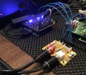
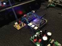
I have a couple of those lying around here.. It looks like removing the 100R resistor will do the trick.
I used this board to do my initial testing on Kali. She made a pretty substantial difference..
I didn't try connecting an external MCLK though.
Thanks! That's what I'll try re: the resistor.
Do you happen to remember your *kernel/dtoverlay* setup when you had it hooked up to the kali? I'm getting dead silence.
I'm using Clive's 384 kernel & squeezelite 80x -- this board works straight from the pi, from i2s out on the D+PRO, but not on the kali192 (did not try the kali384 yet)
I just saw your blog post with the kali, I had it hooked with separate power, but then tried your way thru GPIO... no go, guess I have no idea what overlay to use when the kali is alone-- this one seems to work re: led's
Thanks Again!!, @Greg-- just the messy prototyping stage, getting thing to light up
Attachments
Last edited:
Thanks! That's what I'll try re: the resistor.
Do you happen to remember your *kernel/dtoverlay* setup when you had it hooked up to the kali? I'm getting dead silence.
I was running the ES9023 I2S overlay on Archphile.. It worked both with and without the Kali if I remember correctly.
I'm using Clive's 384 kernel & squeezelite 80x -- this board works straight from the pi, from i2s out on the D+PRO, but not on the kali192 (did not try the kali384 yet)
I can't really imagine what could be wrong. Is Kali outputting an I2S signal?
I just saw your blog post with the kali, I had it hooked with separate power, but then tried your way thru GPIO... no go, guess I have no idea what overlay to use when the kali is alone-- this one seems to work re: led's
My RPi is a B+ so I guess that its power requirements can be met the way I had it hooked up (power through the 1x2 2.54mm header on Kali). For RPis 2+ I guess that the barrel connector on Kali must be used.
I was running the ES9023 I2S overlay on Archphile.. It worked both with and without the Kali if I remember correctly.
What's the config.txt entry for the ESS9023 overlay? (See pic in prev post, my config.txt is there, that does work *without* the kali (raw pi) and with the kali the LED's seem correct) -- but yeah... maybe that shouldn't matter--
I'll try some more things, swap around etc. Thanks!
Last edited:
Found the overlay (dtoverlay=es9023-audio,384k) @Dimdim, thanks-- However, interesting I could only get it to work on the Kali384, not the Kali192. I'll try some more experimenting, it's a little finicky on the kali's (need to cycle power, etc) yet thru raw pi, or D+PRO, it's rock solid & hard to break it (couldn't)
And by the way, the es9023 works at 384K? The specs always say 192... is that concept similar to the PCM51xx & oversample bypass?
Sounds like normal fake tinsel/needley highs i2s from pi (never liked saber, but maybe I've not heard a good implementation, that's why couldn't get myself to spend more than 9 bucks )... but really nice with Kali384 at 384K (and really, any sample rate)! And that is still without MCLK.
Animated, to show the blinking 384K, apologies if it is slightly annoying
@soundcheck, I could continue this on the kali thread, if this is a bit non-mambi related--
Attachments
Last edited:
Scott,
First confirm that the right-most resistor in the 75R resistor array connects to both the MCLK pin on the header on one side AND to pin 13 on the ES9023 on the other side (fourth from the top right as shown in the picture).
Yes... it does.
OTOH, this is one of those situations where how well it works is HIGHLY dependent on how it is connected. Shorter is better. Note in the picture I posted of EUVL's ES9022 board that the output of the clock on that board is one 0604 SMD resistor away from pin 13.
You'd do best to keep those connecting wires to 1" or shorter.
Oh, and I just realized you are connecting to the MCLK output of the HFBD+P instead of a Kali. Not sure that'd be any better than the onboard clock and the ESS ASRC. Will be curious to hear your report.
Agreed re: i2s, meant for board traces-- getting things working here tho, trying to understand i2s more completely, how Clive's linux works, misc. etc.
I need to listen some more before removing the resistor for ext. MCLK... will def. report back about it!
I've been looking at the datasheet of the PCM5122 and trying to decide if it would make a difference to run my HFBD+P in slave mode with the MCLK from the Kali. I'm pretty sure it would work, but not sure it'd make a positive diff. Prob just have to try it someday.
Greg in Mississippi
Cool, did some research myself re D+Pro and the Piano 2.1-- maybe you've seen my post about it on the squeezebox forums. I've just not post that here (kali thread) yet.
There's more going on with the Piano (compared to D+Pro, and other PCM51xx slave mode Dacs) than just good power regulation and ground filtering (inductors). Basically why I've not really compared them seriously yet.
Thanks!!
Last edited:
EDIT: I'm gonna move this to kali thread...
http://www.diyaudio.com/forums/digital-line-level/294940-new-fifo-buffer-rpi-sbcs-49.html#post4891877
http://www.diyaudio.com/forums/digital-line-level/294940-new-fifo-buffer-rpi-sbcs-49.html#post4891877
Last edited:
Change of oscillator
In the second post of this thread Vasilis shows the pcb design of the Mambo LS. It seems easy to change the oscillator for better ones like Crystek or ndk.
Did anybody try this already?
I'm interested in the comparison between Kali reclocker and alternative clocks.
What about the Crystek 957 @ 49.152 Mhz?
60EUR less expensive than the Kali.
Does it work with Clive's 384 kernel?
hmmm, we are thinking to change it...maybe very slow blinking ?
Animated, to show the blinking 384K, apologies if it is slightly annoying
hmmm, we are thinking to change it...maybe very slow blinking ?
I meant annoying re: the animated gif
Hmmm, looking at the board... the "44K/48K Family" Led's are kind of redundant, if you have the option to change the silkscreen, possibly use those for 352.8/384?
Last edited:
- Status
- This old topic is closed. If you want to reopen this topic, contact a moderator using the "Report Post" button.
- Home
- Source & Line
- Digital Line Level
- MamboBerry LS - my new PI-HAT