Got a working Marantz CD-75DX when I was trading stuff to get my hands on genuine TDA1541A SAA7220P/B IC's.
Got enough of the IC's and thought I'd might modify this cd and sell it on to a friend who's into hifi, but hasn't got a clue about soldering etc.
Opened it up for the first time today to take a look.
Been searching for a service manual with no luck, if anyone has one please let me know.
Got enough of the IC's and thought I'd might modify this cd and sell it on to a friend who's into hifi, but hasn't got a clue about soldering etc.
Opened it up for the first time today to take a look.
Been searching for a service manual with no luck, if anyone has one please let me know.
First things first:
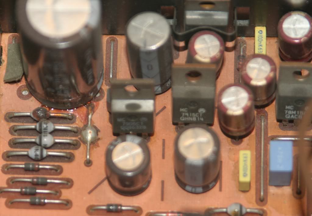
In the first pic you have a leaking electrolytic capacitor. That NEEDS to be replaced at once - it already affected a rectifier diode below.
As a precaution, I would replace all the capacitors in the power supply.
If you have no soldering experience, don't attempt mods, you will just trash it. Thru-the-hole integrated cips with many pins (like is your TDA1541 and OpAmps) are difficult to remove (without damaging the PCB) by an unexperienced person.
Start your soldering experiments with something else.
Last edited:
First things first:
In the first pic you have a leaking electrolytic capacitor. That NEEDS to be replaced at once - it already affected a rectifier diode below.
As a precaution, I would replace all the capacitors in the power supply.
Yes I noticed that.
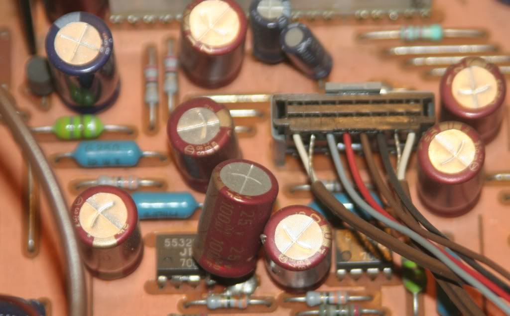
The cap between the opamp and gnd can't be standard? Someone has to have been tinkering with this cd-player before.
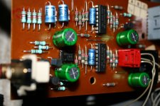
That cap is not stadard - didn't fit in the original place I guess. Similar board was used in some Phillips players see below (I used sockets when i was testing different OpAmps - in the picture are the LM4562 that remained).
Attachments

Last edited:
PSU will be almost identical to the 65. I put pics of what and where when I did my pals 65SE in your CD50 /60 thread. Most of these players share much commonality.
Some decent caps though, Elna Cerafine amongst others.
Bin em they'll be knackered, and put ZLG's on analogue rails and Solid Polymer on dig........sound familiar????😕🙄
Use Panasonic FC's as smoothers etc etc............🙄
Those 25 year old caps will be shot!!!!!.................🙄
Surely you cant need 3 or 4 threads running all saying the same thing for the same players or DAC with different badges???😱😱😱😱
Sorry UV, but I haven't asked any questions here, except for asking if anyone had/or knew where to get a service manual for this cd-player.
I didn't know that the PSU was almost identical to one that you posted pics of in another thread.
I didn't know that the PSU was almost identical to one that you posted pics of in another thread.
First things first:
In the first pic you have a leaking electrolytic capacitor. That NEEDS to be replaced at once - it already affected a rectifier diode below.
As a precaution, I would replace all the capacitors in the power supply.
If you have no soldering experience, don't attempt mods, you will just trash it. Thru-the-hole integrated cips with many pins (like is your TDA1541 and OpAmps) are difficult to remove (without damaging the PCB) by an unexperienced person.
Start your soldering experiments with something else.
I ment to say that my friend has no soldering experience. Sorry if that was unclear. 🙂
Sorry UV, but I haven't asked any questions here, except for asking if anyone had/or knew where to get a service manual for this cd-player.
I didn't know that the PSU was almost identical to one that you posted pics of in another thread.
Don't appologise!!! ;-) I am surprised you didn't recognise the main board tho!! It'll be very similar if not identical to this

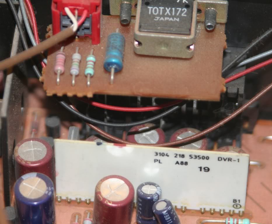
Very similar, but what's the white board sticking up from the pcb just before outputs on the 75dx?
That cap is not stadard - didn't fit in the original place I guess. Similar board was used in some Phillips players see below (I used sockets when i was testing different OpAmps - in the picture are the LM4562 that remained).
I doubt they used Cerafines, I think someone might have modded this cd-player before. The leaky PS cap is also Elna.
Usually you see mostly nichicons or similar...
Last edited:
Those cerefines will be original. The cerefines you see in my pic were as std ;-)
Did the 75 have variable volume outputs? That White board could be the volume control preamp. It'll be something like that which will be the difference between 65 & 75
Did the 75 have variable volume outputs? That White board could be the volume control preamp. It'll be something like that which will be the difference between 65 & 75
Those cerefines will be original. The cerefines you see in my pic were as std ;-)
Did the 75 have variable volume outputs? That White board could be the volume control preamp. It'll be something like that which will be the difference between 65 & 75
No variable outputs, just fixed and digital via coaxial and toslink.
Will go about swapping caps etc soon enough.
Really wish I could find a service manual though, makes it that much easier.
Headphones maybe???
I don't think so, would be rather poor layout placing the circuitry for them all the way back by the outputs?
Where else do you think the audio will be for the headphones? The headphones amp will be after the I/V and buffer stage (opamp) on the analogue side of the TDA. In the cd50, they use a similar amp module for both the phones and variable out on the module board you've removed from that player 😉
Where else do you think the audio will be for the headphones? The headphones amp will be after the I/V and buffer stage (opamp) on the analogue side of the TDA. In the cd50, they use a similar amp module for both the phones and variable out on the module board you've removed from that player 😉
Didn't even think that far 😱😱
- Status
- Not open for further replies.
- Home
- Source & Line
- Digital Source
- Marantz CD-75dx