I've had this sitting around not doing anything.
Before I start some ground up builds might as
well get this going before I go further.
I have an MC250 non working.
The MC250 should be the simplest to get going.
One channel doesn't work, so as long as I'm in there
I might as well upgrade the ICs and the Caps.
It makes no sense to fix one channel and
have the other channel sound differently.
These are the transistors that were specified when
the amp was manufactured. Always good to double
check to make sure they are the current and correct devices.
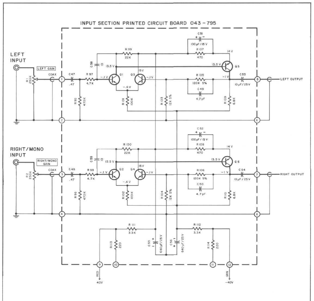
Input PCB
Q1,Q2 NPN Transistor 3 Pin 132-054 2N5210 50 200 600 100uA
Q3, Q4 NPN Transistor 3 Pin 132-054 2N5210 50 200 600 100uA
Q5, Q6 PNP Transistor 3 Pin 132-056 2N2087 50 250 800 100uA
OUTPUT DRIVER PCB
Q7, Q8 PNP Transistor TO-92 13C 132-056 2N2087 50 250 800 100uA
Q9, Q10 PNP Transistor TO-92 13C 132-056 2N2087 50 250 800 100uA
Q15, Q16 NPN Transistor 3 Pin 132-021 2N3569 40 90 30
Q17, Q18 PNP Transistor 3 Pin 132-032 2N3645 60 50 100
OUTPUT DRIVERs PCB
Q11, Q12 NPN Transistor TO-66 132-515 132-028 2N3738 120 65 50
OUTPUT Transistors (on heatsink) TO-66
Q19, Q20 NPN Transistor Output TO-66 132-524 132-023 2N3767 90 25 150
Q21, Q22 PNP Transistor Output TO-66 132-530 132-023 2N3767 90 25 150
OUTPUT Transistors (on heatsink) TO-3
Q23, Q24 NPN Transistor Output 132-070 2N5303 80 30 90 5A
Q25, Q26 NPN Transistor Output 132-070 2N5303 80 30 90 5A
Here is the link to the Input Board Schematic:
diyAudio
Might was well start a Wiki for this too as then hopefully we can put
all the information in one place and won't have to have a lot of threads
that other DIYer have to go through to figure everything out.
Started the wiki and will put links and resources all in one spot.
Post #2 and #5 I was trying to put into table format for simpler
reading and recognition. It appears I'm still HTML challenged.
But still trying.
Before I start some ground up builds might as
well get this going before I go further.
I have an MC250 non working.
The MC250 should be the simplest to get going.
One channel doesn't work, so as long as I'm in there
I might as well upgrade the ICs and the Caps.
It makes no sense to fix one channel and
have the other channel sound differently.
These are the transistors that were specified when
the amp was manufactured. Always good to double
check to make sure they are the current and correct devices.
Input PCB
Q1,Q2 NPN Transistor 3 Pin 132-054 2N5210 50 200 600 100uA
Q3, Q4 NPN Transistor 3 Pin 132-054 2N5210 50 200 600 100uA
Q5, Q6 PNP Transistor 3 Pin 132-056 2N2087 50 250 800 100uA
OUTPUT DRIVER PCB
Q7, Q8 PNP Transistor TO-92 13C 132-056 2N2087 50 250 800 100uA
Q9, Q10 PNP Transistor TO-92 13C 132-056 2N2087 50 250 800 100uA
Q15, Q16 NPN Transistor 3 Pin 132-021 2N3569 40 90 30
Q17, Q18 PNP Transistor 3 Pin 132-032 2N3645 60 50 100
OUTPUT DRIVERs PCB
Q11, Q12 NPN Transistor TO-66 132-515 132-028 2N3738 120 65 50
OUTPUT Transistors (on heatsink) TO-66
Q19, Q20 NPN Transistor Output TO-66 132-524 132-023 2N3767 90 25 150
Q21, Q22 PNP Transistor Output TO-66 132-530 132-023 2N3767 90 25 150
OUTPUT Transistors (on heatsink) TO-3
Q23, Q24 NPN Transistor Output 132-070 2N5303 80 30 90 5A
Q25, Q26 NPN Transistor Output 132-070 2N5303 80 30 90 5A
Here is the link to the Input Board Schematic:
diyAudio
Might was well start a Wiki for this too as then hopefully we can put
all the information in one place and won't have to have a lot of threads
that other DIYer have to go through to figure everything out.
Started the wiki and will put links and resources all in one spot.
Post #2 and #5 I was trying to put into table format for simpler
reading and recognition. It appears I'm still HTML challenged.
But still trying.
Last edited:
Vceo or Hfe Hfe at Ic
Transistors
Vds or Yfs or Yfs or Vgs
(Volts) (min) (max)
Q1 ,2 NPN Transistor 3 Pin 132-054 2N5210 50 200 600 100uA
Q3, 4 NPN Transistor 3 Pin 132-054 2N5210 50 200 600 100uA
Q5,6 PNP Transistor 3 Pin 132-056 2N2087 50 250 800 100uA
Q7,8 PNP Transistor TO-92 13C 132-056 2N2087 50 250 800 100uA
Q9.10 PNP Transistor TO-92 13C 132-056 2N2087 50 250 800 100uA
Q11 ,12 NPN Transistor 132-515 132-028 2N3738 120 65 50
Q15,16 NPN Transistor 3 Pin 132-021 2N3569 40 90 30
Q17,18 PNP Transistor 3 Pin 132-032 2N3645 60 50 100
Q19,20 NPN Transistor Output TO-66 132-524 132-023 2N3767 90 25 150
Q21 ,22 PNP Transistor Output TO-66 132-530 132-023 2N3767 90 25 150
Q23,24 NPN Transistor Output 132-070 2N5303 80 30 90 5A
Q25,26 NPN Transistor Output 132-070 2N5303 80 30 90 5A
Wiki
The wiki has started, feel free to add some content to it.
Pull down Wiki: List and go to it.
The wiki has started, feel free to add some content to it.
Pull down Wiki: List and go to it.
As this is also a learning project for me I'll post the measurements when I can find the
notes I took of them. Then, I have to hunt down the transistors...
notes I took of them. Then, I have to hunt down the transistors...
These are the transistor test using the diode function on fluke.
Read under the B-E, r starts with the red + probe on the base, the black - on emitter.
Input Board
Q1 NpN
B-E
r OL
b .64
C-E
r OL
b .62
Q3 NpN
B-E
r OL
b .64
C-E
r OL
b .3 rising.
Q5 - PnP
B-E
r OL
b 2.9
C-E
r OL
b 2.9 rising
Q2 - NpN
B-E
r OL
b .64
C-E
r OL
b.29
Q4- NpN
B-E
r OL
b .63
C-E
r .8
b OL
Q6 - PnP
BE
r .65
b 2.9
r 2.9 to OL
b 1.9 ++ 2/9
Last edited:
Well that post didn't t urn out too well.
I'll try to put that into a table.
for some reason that seems to give me problem.
Here are some pics of where I am:
HTML Linked
HTML PIC
IMG (pasted)
IMG (linked)
IMG (pic) doesn't work.
Trying to figure out which work in thumbnail mode.
![IMGDEAD]](/community/proxy.php?image=http%3A%2F%2Fwww.diyaudio.com%2Fforums%2F%3Ca+href%3Dhttp%3A%2F%2Fsmg.photobucket.com%2Fuser%2FTheAmpNerd%2Fmedia%2FMcIntosh%2F03.MC250BoardTest3_zpskhos9mgn.jpg.html+target%3D_blank%3E%5BIMGDEAD%5Dhttps%3A%2F%2Fimg.photobucket.com%2Falbums%2Fv209%2FTheAmpNerd%2FMcIntosh%2F03.MC250BoardTest3_zpskhos9mgn.jpg%5B%2FIMGDEAD%5D&hash=3cf93b420a3ebbd479e17f97bee39227)
I'll try to put that into a table.
for some reason that seems to give me problem.
Here are some pics of where I am:
HTML Linked
HTML PIC
IMG (pasted)
An externally hosted image should be here but it was not working when we last tested it.
IMG (linked)
An externally hosted image should be here but it was not working when we last tested it.
IMG (pic) doesn't work.
Trying to figure out which work in thumbnail mode.
Last edited:
First Test w/New Electrolytics Input Board
After Max Output before clipping, square wave testing at -2dB:

Here is the sine wave at -2dB, Vp-p:
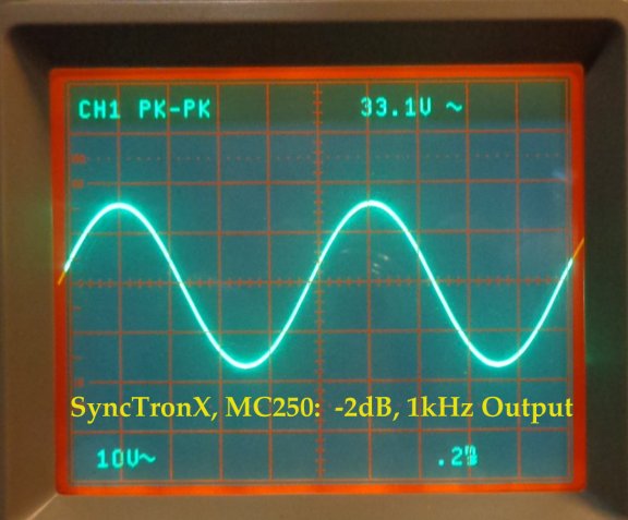
Here, Selecting Square Wave from the Leader LFG-1300s:
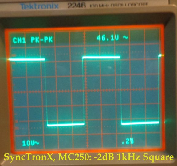
10kHz, Square Wave:
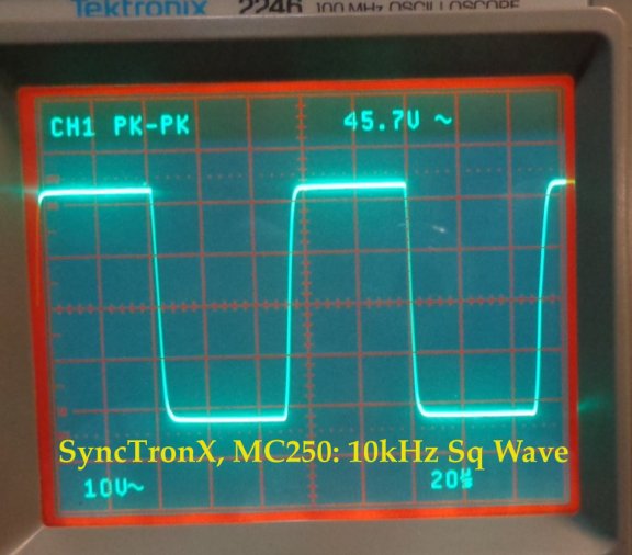
20kHz Square Wave:
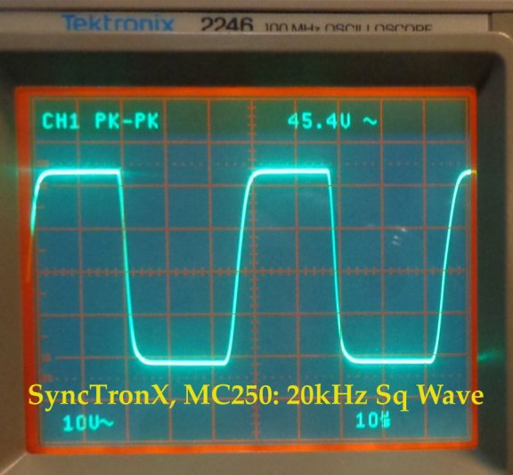
Finally, the 50 Hz Square Wave:
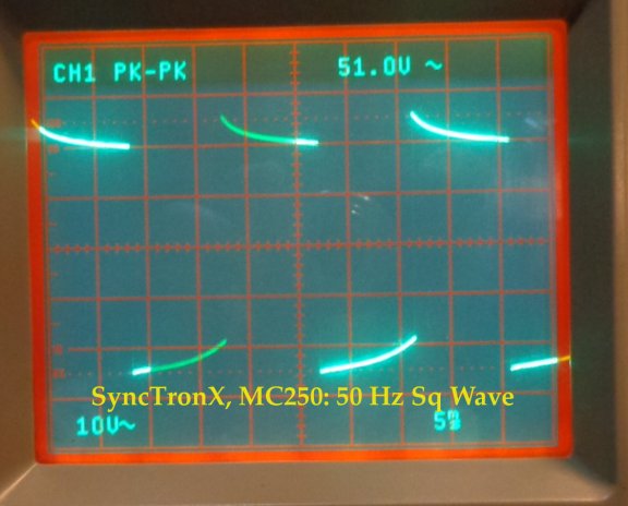
Note: I do the 50 Hz square wave last as it seems to really drive the amp hard,
you can hear the whole amp start vibrating and getting hot quickly.
These tests were performed as outlined in:
C. Schrock. (1975.) The Tektronix Cookbook of Standard Audio Tests:
sing the 5L4N low frequency spectrum analyzer.
[Sync NOTE: 5L4N is not required for these
tests]. Tektronix, Inc. Beaverton, OR, U.S.A. LINK
After Max Output before clipping, square wave testing at -2dB:
Here is the sine wave at -2dB, Vp-p:
Here, Selecting Square Wave from the Leader LFG-1300s:
10kHz, Square Wave:
20kHz Square Wave:
Finally, the 50 Hz Square Wave:
Note: I do the 50 Hz square wave last as it seems to really drive the amp hard,
you can hear the whole amp start vibrating and getting hot quickly.
These tests were performed as outlined in:
C. Schrock. (1975.) The Tektronix Cookbook of Standard Audio Tests:
sing the 5L4N low frequency spectrum analyzer.
[Sync NOTE: 5L4N is not required for these
tests]. Tektronix, Inc. Beaverton, OR, U.S.A. LINK
Here is the next batch of pics after changing the input boards transistors.
Capt Grog had an interesting suggestion to not use the Toshiba 2sc2240BL,
about 110 voltage rating.
because while the voltage rating on these transistors is high using a
lower voltage 50 Volt, hi gain transistor like the Fairchild SS9014 might
be a better choice. This McIntosh MC250 has a 40 volt inputs on the
B+ and -40 volt on the B-.
These are the pics and basic testing using these transistors.
I'll Start with the test gear then go through the square wave testing.
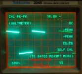
The Test Gear:


Here are the level measurements:


Then the Square waves:


Much improved 50 Hz response compared to that in post 7. Linked
below for your convenience:

Most recent is just above this 50Hz Sq Wave.
Capt Grog had an interesting suggestion to not use the Toshiba 2sc2240BL,
about 110 voltage rating.
because while the voltage rating on these transistors is high using a
lower voltage 50 Volt, hi gain transistor like the Fairchild SS9014 might
be a better choice. This McIntosh MC250 has a 40 volt inputs on the
B+ and -40 volt on the B-.
These are the pics and basic testing using these transistors.
I'll Start with the test gear then go through the square wave testing.
The Test Gear:
Here are the level measurements:
Then the Square waves:
Much improved 50 Hz response compared to that in post 7. Linked
below for your convenience:
Most recent is just above this 50Hz Sq Wave.
Last edited:
Trying to put some thumbnail images that can be expanded.
And of course adding the text below deleted the pictures. : )
Left: Before transistor change
Right: After transistor change
And of course adding the text below deleted the pictures. : )
Left: Before transistor change
Right: After transistor change
Attachments

Last edited:
Took a set of readings and put the bottom on,
connected her into the system and powered her
on. Working fine. Images rather well. Didn't even
get warm after and all night playing.\
It will take a little bit to get it where I want it to be.
I didn't notice any problems in the system and it sounds
similar to the Dynaco Series II ST-70.
Moving around from room to room you will notice differences
in tone from the tube amp. As the MC250 warmed up over
the hours, it started sounding more and more solid statish.
I'll probably want to do some changes to the output driver PCBs
along with changing some of caps on the input board as well.
I'm just not sure which is the best way to go and which caps
to fool with.
I definitely know the two big power caps need to go.
They are feeling their age the farads are testing high.
Will post updates as I get to them with pics.
A new problem now appears to have presented itself to me.
About and hour ago on power the amp made a series of high frequency
screams or screeches. This is from the amp with no signal to it,
with the amp connected to the switched power connection on the back
of the pre amp.
Each screech was greater than 120 dB maybe 130 or even 140dB I'm guessing
probably 2500 Hz or higher. Each screech, followed by a second of silence,
than another, followed by silence...alsmost as if each set of power transistors
was turning on.
My ears are still ringing from it and I have a loss of HF hearing because if it.
Holy Smokes. I was worried about damaging my speakers horns...
I'm more worried about my ears and my little girls ears.
Thinking the setting on the input gain wouldn't matter as it wasn't from
the pre amp any way. It was from the amp itself.
So what kind of output protection or cut power to speakers
at power on are available or should I be looking at something
in the amp itself. Not sure what though.
My ears aren't doing well right now either.
Cheers,
- Status
- Not open for further replies.
- Home
- Amplifiers
- Solid State
- McIntosh MC250 Repair/Upgrade