I'm wondering is there any easy way to see crossover spikes using oscilloscope, just to make it easier to bias output stage. I dont have THD analyzer so looking for some "easy to make" solutions.
How about this one:
Good low thd 1kHz sine wave generator -> Power amplifier -> simple 1kHz deep notch filter (active or passive).
Then using two channels of the scope to see and compare amp output to the notch filter output?
How about this one:
Good low thd 1kHz sine wave generator -> Power amplifier -> simple 1kHz deep notch filter (active or passive).
Then using two channels of the scope to see and compare amp output to the notch filter output?
If the crossover distortion is low, and on most well-designed amps it is low (circa 0.01% to tens of ppm), you will have a hard time seeing it on a scope. If you have an audio interface, you have a distortion analyzer for cheap. With a sound card and REW, you can easily see the distortion with common tools and very little gear.
Howto - Distortion Measurements with REW
Howto - Distortion Measurements with REW
Signal defect selector. Everything, not just a crossover.
Стр. 22 журнала <<Радио>> № 1 за 1993 год
Стр. 22 журнала <<Радио>> № 1 за 1993 год
You won't see crossover distortion on a scope once a correctly operating output stage has more than just a couple of milliamps bias let alone tens or hundreds of milliamp bias.
There are rules of thumb relating bias current to output stage topology that might help you get close but be aware that commercial designs are often under biased to aid cool running and reliability, mainly due to less than optimal heatsinking.
There are rules of thumb relating bias current to output stage topology that might help you get close but be aware that commercial designs are often under biased to aid cool running and reliability, mainly due to less than optimal heatsinking.
Transformer connected between Vas and output
Стр. 39 журнала <<Радио>> № 3 за 1975 год
Стр. 39 журнала <<Радио>> № 3 за 1975 год
To be honest, I find it quite difficult to even look at 1% THD on a scope.
The best way to look at crossover distortion is to use the residual output of a THD analyzer and connect it to a scope, crossover distortion is pretty easy to spot then, it looks like little spikes.
Exactly the thing I want to see. So I'm trying to DIY somekind of THD analyzer "feed through" circuit. I think it is just a deep fundamental notch filter of some kind? So that only distortion components will pass?
Last edited:
Try doing a difference type display. Set scope to x-y, adjust oscilloscope gain until sinewave disappears. Display will show the difference between the input and output. Run amplifier with load. Sometimes feedback will compensate for spikes with no load. You need two channels of scope to see one channel of amplifier. So to do both at same time, need 4 channel scope.
Interesting method. I may try that
")
Exactly the thing I want to see. So I'm trying to DIY somekind of THD analyzer "feed through" circuit. I think it is just a deep fundamental notch filter of some kind? So that only distortion components will pass?
Yes you can use a very steep notch to cancel out the fundamental, it has to be a very good notch though, perhaps something like a Wien-Robinson or State Variable filter.
Try doing a difference type display. Set scope to x-y, adjust oscilloscope gain until sinewave disappears. Display will show the difference between the input and output. Run amplifier with load. Sometimes feedback will compensate for spikes with no load. You need two channels of scope to see one channel of amplifier. So to do both at same time, need 4 channel scope.
Well, I only got straight 45 deg. line. While increasing input frequency past 10kHz, the line was getting oval shape (phase shift).
Scopes really are at best 8bit maybe 10bit resolution - you won’t be able to see much better than 1% to 0.1% THD (very high).
Try the REW and sound card. Every computer has a microphone input you can use.
Make sure you use an attenuator (10:1) in order to prevent over voltage from hurting your audio input front end.
Here is measurement of capability of a Focusrite using a 2ppm 1kHz Akitika oscillator - can get as low as 0.00036% THD.
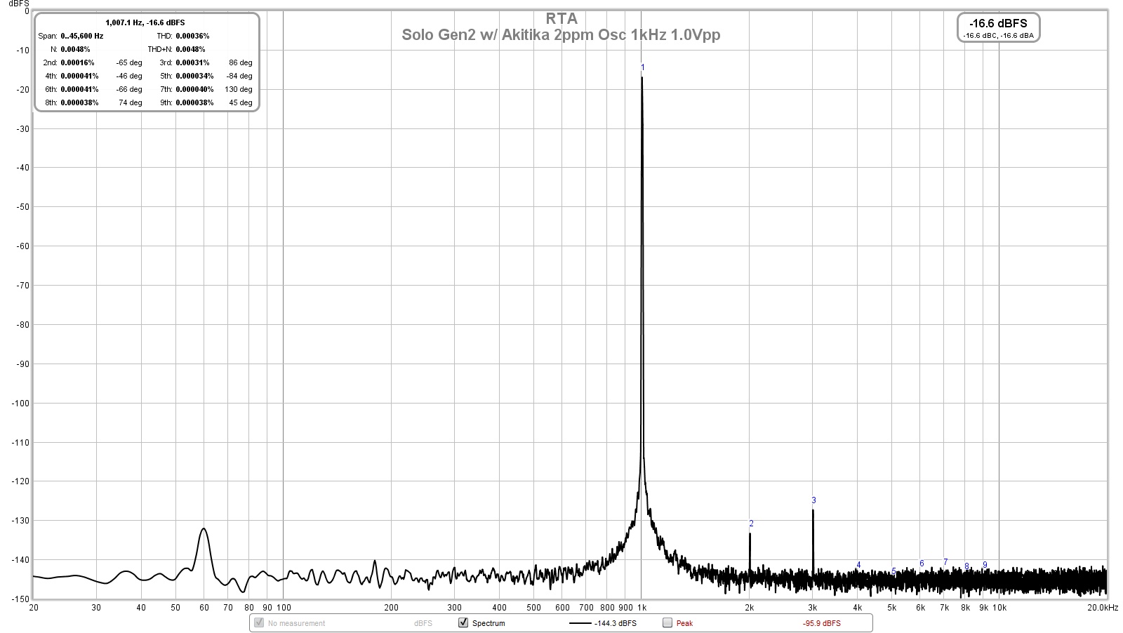
Last edited:
Well, I only got straight 45 deg. line. While increasing input frequency past 10kHz, the line was getting oval shape (phase shift).
Lissajous curve - Wikipedia
Well, I only got straight 45 deg. line. While increasing input frequency past 10kHz, the line was getting oval shape (phase shift).
45 line is x/y. I meant x minus y, or invert x and x+y (or a+b and a (or b) inverted. Maybe called differential mode. Regular sweep. sorry about the confusion. (It's confusing to me, too.)
He said he was planning to use a notch to notch out the fundamental. In that case, the scope *may* show the xover. But even if you see the xover, it doesn't really say a lot, except that it is present. It is very hard to get some quantitative info.
But I agree that the simplest, high-resolution solution is a sound-card and some free software. And even the PC build-in sound-card may do, depending on the amp tested.
Jan
But I agree that the simplest, high-resolution solution is a sound-card and some free software. And even the PC build-in sound-card may do, depending on the amp tested.
Jan
But even if you see the xover, it doesn't really say a lot, except that it is present. It is very hard to get some quantitative info.
Enough to trim the output stage bias for lowest THD.
There are two fundamental ways to measure / look at distortion that I tried:
1. Compare amp input to divided-down amp output. A classical 3-opamp instrumentation amp with very good opamps and resistors matched to <0.01% will do. Note you need an adjustable first order low pass at the direct input to make up for limited bandwidth of the amp. This is basically a distortion magnifier with magnification of 10.000x and no THD analyser needed. Manual adjustment is a hassle and everything under say 0.01% THD gets buried in noise. But this is the most intuitive method.
2. Filter out the fundamental with a very deep notch and look at what is left through a magnifier. The notch in my case was an active double double T, or two active double Ts cascaded. This way you can keep the feedback divider a moderate level and you do not loose attenuation if the frequency shifts 0.01Hz. (A single notch with 100% feedback gets so steep it is impossible to keep it in tune with the generator.) My magnifier was an AD797 at a gain of 1000x and measurement limit is 0.00003% with a 140dB notch. Note this is far below the noise, only the 128x averaging of the digital scope digs it out. And you can nearly keep your hand at the frequency adjust of the generator! 10.61K resistors were matched to 0.1Ohm and 15nF capacitors to 5pF to get this performance on a perf board. I would like to know if the 0.00003% come from the generator or the active notch.
Thank you for tips!
Maybe i'll give a try for REW. Im using it for speaker measurements and analysis (freq. response, thiele small parameters etc).
I just made 1kHz passive twin-t notch filter which I was trying. Active filter using op amp with feedback would be much better indeed. I can easily make it too but first I need to figure out the best simple method
Here is a o.scope screen from very old amplifier test, see that lower trace where crossover distortion spikes are clearly visible. How did they do that? I dont know for sure but possibly it is indeed notch filtered and magnified fundamental. That's what Im looking for
- Home
- Amplifiers
- Solid State
- Measuring crossover distortion / bias