
Oh yes, good analogy. And the sine burst is like opening a book in the middle, starting to read a page, and it begins in the middle of a sentence that means nothing.
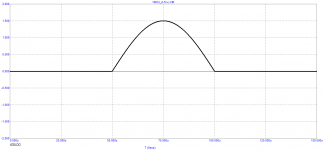
By the way, why not use this test signal instead?
View attachment 1081254
peufeu, can you read any page in the middle of a book? And why do you think that the amplifier should not accurately amplify any audio signals, the spectrum of which, according to some sources, extends up to 90 kHz or more. As for pulse signals, they are widely used for testing, such as rectangular.
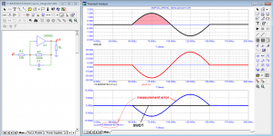
An ideal amplifier (01 - no signal delay, group delay=0) does not introduce any distortion (neither vector nor speed).
Even an ideal amplifier that does not introduce non-linear distortions, but has a signal propagation delay of 15 ns (02) introduces vector distortions up to -60 dB (SWDT test) and high-speed distortions, the peak level of which reaches 0.00004%.
If I understood correctly the author of this post https://www.diyaudio.com/community/threads/sound-quality-vs-measurements.200865/post-2868515 guessed to use one half-cycle of the sine (03) to reveal the difference in amplification of signals by different amplifiers. And he found her.
In a real amplifier operating on a real load, along with a negative feedback signal, not only distortion products but also back-EMF signals from the acoustic system arrive at the summation point, which contributes to the expansion of the spectrum of harmonic components. At the same time, with significant delays in the passage of the signal, the smallest details of the sound material are smeared, the nuances responsible for the naturalness of the sound fall out, and higher harmonics are added to which human hearing is very sensitive. In this case, the sound becomes “dead”, different from live sound, and under certain conditions (depending on the group delay behavior not only in the audio range, but far beyond it) annoying - typically “transistor”.
Attachments
It should, but the tests that will tell you if it does don't include using unlimited bandwidth signals that can only exist inside a computer...And why do you think that the amplifier should not accurately amplify any audio signals
Sure, but you did not model an ideal amplifier with 15ns delay. You modeled a first order lowpass filter with -3dB frequency at 10MHz and a gain of 19.986. Then you compared its response to an ideal amplifier with 15ns delay and found a difference ;DEven an ideal amplifier that does not introduce non-linear distortions, but has a signal propagation delay of 15 ns (02) introduces vector distortions up to -60 dB (SWDT test) and high-speed distortions, the peak level of which reaches 0.00004%.
SWDT without compensating for delay is meaningless, so I'm not looking at the middle plot.
The label "measurement error" corresponds to the gain being 19.986 and not 20, of course.
SWDT according to Hafler is nothing but vector error according to Jiri Dostal.
vector errors are measured as is, without delay compensation. Compensation method for measuring all types of distortion provides for delay compensation
vector errors are measured as is, without delay compensation. Compensation method for measuring all types of distortion provides for delay compensation
Attachments
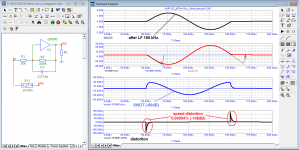
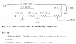
the Hafler test measures vector errors (what Dostal described), and the Baxandall test is a compensation method for measuring distortion at the input signal level. The output signal of the amplifier under test is then normalized to the level of the input signal. At the same time, the distortions introduced by the amplifier are also weakened by a factor of Ku. To improve the accuracy of measurements, it is better to measure at the output voltage level of the amplifier. To do this, the input signal must be normalized to the output level and delayed by the group delay of the amplifier.
In this case, the phase is not discussed.
In this case, the phase is not discussed.
Attachments
This is how negative feedback works - it mixes the input signal with the normalized output signal in the comparison nodeVector error is important if the circuit will mix the input and output signals,
Ahh yes, the filter works, but it is not as was described a pre-correction later compensated with another something. Calling it a pre-correction is misleading, it is just a filter. That is why we call it a filter, not some fancy misleading name.It is a question or a statement?
Take for example the crunch filter of scratched vinyl records. How does the filter algorithm know how the plate is scratched, but the filter works...
There is a similar situation here, I made a similar corrector and it really makes switching distortions less noticeable, for this I took an amplifier with an output to Shiklai Douglas Self, because it has a lot of those switching distortions......
Are you saying there is a filter somewhere to prevent crossover distortion? That would be very interesting. Do you have more info on how it works?
Jan
Cross-Over Distortion, Bias and Group Delay
It is known that the main distortions are introduced by the output stage. Cross-Over distortion is highly dependent on the quiescent current. In class AB amplifiers, the emitter resistors of the output transistors also affect crossover distortion. Therefore, you have to choose a compromise between temperature stabilization and crossover distortion.
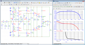
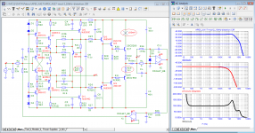
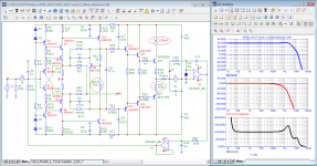
For cloning, the relatively simple APEX AX17 amplifier is popular among radio amateurs. Let's take a look at its main characteristics: Bode diagram, loop gain, distortion at a frequency of 10 kHz and a burst at a frequency of 20 Hz.
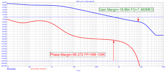
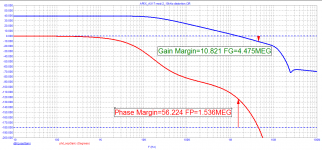
From the Bode diagram, you can see that the bandwidth at the bottom is -3 dB at about 70 Hz! (Fig. 01). Group delay above 10 kHz is about 300 ns (which would seem not so much compared to other amplifiers). The loop gain in the audio band is not constant, in the low-frequency region about 50 dB, and at a frequency of 20 kHz - 30 dB.
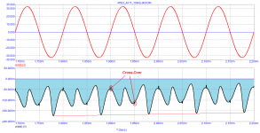
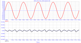
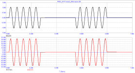
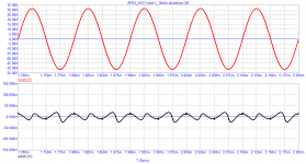
The distortion products of a 10 kHz signal even at the 22-nd period have a significant DC offset, the transient process is still far from over. The distortion products show a small amount of crossover distortion compared to non-linear distortion. The input burst with a frequency of 20 Hz is passed through a 100 kHz filter, while the output signal has clearly expressed both linear distortions (low output signal amplitude) and significant waveform distortions, especially in the first period and at the end of the bursts.
Let's try to reduce the signal propagation delay time in the entire audio range. To do this, we will turn the amplifier into a DC amplifier using an integrator and slightly alter the VAS.
It is known that the main contribution to the nonlinear distortion is made by the output stage. Therefore, for the purity of the experiment, we will leave it unchanged (with the same current modes). As a result of a little refinement, the loop gain is about 40 dB and is constant throughout the entire audio range. The distortion products of the 10 kHz signal are significantly reduced and have no DC bias. The 20Hz burst signal is also amplified without visible distortion.
In order to reduce switching distortion, emitter resistors are reduced from 0.33 Ohm to 0.1 Ohm. But even with 0.33 Ohm resistors, switching distortions are small due to the group delay reduction by more than 3 times.
It is known that the main distortions are introduced by the output stage. Cross-Over distortion is highly dependent on the quiescent current. In class AB amplifiers, the emitter resistors of the output transistors also affect crossover distortion. Therefore, you have to choose a compromise between temperature stabilization and crossover distortion.
For cloning, the relatively simple APEX AX17 amplifier is popular among radio amateurs. Let's take a look at its main characteristics: Bode diagram, loop gain, distortion at a frequency of 10 kHz and a burst at a frequency of 20 Hz.
From the Bode diagram, you can see that the bandwidth at the bottom is -3 dB at about 70 Hz! (Fig. 01). Group delay above 10 kHz is about 300 ns (which would seem not so much compared to other amplifiers). The loop gain in the audio band is not constant, in the low-frequency region about 50 dB, and at a frequency of 20 kHz - 30 dB.
The distortion products of a 10 kHz signal even at the 22-nd period have a significant DC offset, the transient process is still far from over. The distortion products show a small amount of crossover distortion compared to non-linear distortion. The input burst with a frequency of 20 Hz is passed through a 100 kHz filter, while the output signal has clearly expressed both linear distortions (low output signal amplitude) and significant waveform distortions, especially in the first period and at the end of the bursts.
Let's try to reduce the signal propagation delay time in the entire audio range. To do this, we will turn the amplifier into a DC amplifier using an integrator and slightly alter the VAS.
It is known that the main contribution to the nonlinear distortion is made by the output stage. Therefore, for the purity of the experiment, we will leave it unchanged (with the same current modes). As a result of a little refinement, the loop gain is about 40 dB and is constant throughout the entire audio range. The distortion products of the 10 kHz signal are significantly reduced and have no DC bias. The 20Hz burst signal is also amplified without visible distortion.
In order to reduce switching distortion, emitter resistors are reduced from 0.33 Ohm to 0.1 Ohm. But even with 0.33 Ohm resistors, switching distortions are small due to the group delay reduction by more than 3 times.
Attachments
-
 01_APEX_AX17_Bode.png36.3 KB · Views: 80
 -
 02_APEX_AX17_Loop-Gain.png12.7 KB · Views: 79
 -
 03_APEX_AX17_10kHz-distortion.png14 KB · Views: 60
 -
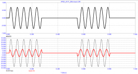 04_APEX_AX17_20Hz-burst.png13.2 KB · Views: 83
 -
 01_APEX_AX17_mod-2_Bode.png40.7 KB · Views: 75
 -
 02_APEX_AX17_mod-2_Loop-Gain.png13.2 KB · Views: 81
 -
 03_APEX_AX17_mod-2_10kHz-distortion.png13.3 KB · Views: 65
 -
 04_APEX_AX17_mod-2_20Hz-burst.png13.9 KB · Views: 74
 -
 01a_APEX_AX17_mod-1_Bode.png40.9 KB · Views: 71
 -
 03a_APEX_AX17_mod-1_10kHz-distortion.png27.4 KB · Views: 82
I was experimenting with bjt power buffers, just the output stage, tested thd vs bias, and settled at ~0.3A per device, for 3 pair output pair driven by the same bjt pair. No negative feedback, thd was very low, ~0.008%. Great soundstage. Low wattage though. I compared 5 different types of most common power bjt, but found little difference. Best way to combat crossover distortion is high bias.
Last edited:
What was the load current? You might have been in class A.I was experimenting with bjt power buffers, just the output stage, tested thd vs bias, and settled at ~0.3A per device, for 3 pair output pair driven by the same bjt pair. No negative feedback, thd was very low, ~0.008%. Great soundstage. Low wattage though. I compared 5 different types of most common power bjt, but found little difference. Best way to combat crossover distortion is high bias.
Jan
And the sine burst is like opening a book in the middle...
So should the amplifier accurately amplify audio signals from the first half cycle?
Attachments
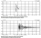
Yes, definitelySo should the amplifier accurately amplify audio signals from the first half cycle?
I'm interested in the thread:
https://www.diyaudio.com/community/threads/sound-quality-vs-measurements.200865/post-2833823
But I was able to read less than 1/10. Can anyone tell me what the final conclusions are.
https://www.diyaudio.com/community/threads/sound-quality-vs-measurements.200865/post-2833823
tvrgeek
«… is there is some effect that is not currently understood that causes differences in the audible perception of an amplifier. Something is effecting the dynamic transfer function.»But I was able to read less than 1/10. Can anyone tell me what the final conclusions are.
Based on the last few pages of that thread the final conclusion (or climax) was that the high priestess of jitterati went off rails.I'm interested in the thread:
https://www.diyaudio.com/community/threads/sound-quality-vs-measurements.200865/post-2833823
tvrgeek
«… is there is some effect that is not currently understood that causes differences in the audible perception of an amplifier. Something is effecting the dynamic transfer function.»
But I was able to read less than 1/10. Can anyone tell me what the final conclusions are.
Thanks bohrok2610!
If I understand correctly, this is the final verdict:
https://www.diyaudio.com/community/threads/sound-quality-vs-measurements.200865/post-6673896
If I understand correctly, this is the final verdict:
https://www.diyaudio.com/community/threads/sound-quality-vs-measurements.200865/post-6673896
anatech
«That discussion will never end, take years and really not conclude with anything useful.»One cycle makes it hard to estimate frequency and amplitude, but not impossible. Basic approach is model a pure tone and perform least-squares optimization till the model matches as best it can, take the difference for the residual.doesn't work that easily in real life.
Far better to just measure 30+ cycles and window then you don't need to worry about sampling rates, noise etc
One approach I've used is to use a bunch of cycles, perhaps 50 to 100ms sample for 1kHz, and first determine the zero crossings to get a good estimate of frequency. You build your sine wave model (freq, phase, amplitude), and correlate against it using the first half of the signal and separately the second half of the signal. The average and difference of the two correlation results can be used to refine the frequency and phase and amplitude - repeat 2 or 3 times and you've got a good fit, take the difference and repeat for measuring each harmonic, subtracting them out one-by-one (don't do the zero crossing for harmonics, you know the frequency anyway).
No FFT needed.
- Home
- Amplifiers
- Solid State
- Measuring crossover distortion / bias