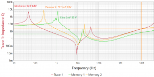
An electrolytic capacitor's impedance versus frequency curve is plotted in Figure 1 below. At low frequencies, impedance falls as frequency rises, and the device behaves like a textbook capacitor. At the frequency where the capacitor's impedance falls to "ESR" (equivalent series resistance), the capacitor begins to operate like a resistor: impedance is constant with frequency. And finally, impedance begins to RISE as frequency rises, and the electrolytic capacitor operates like an inductor.
I got interested in this "inductor" mode of operation, and wanted to measure the Equivalent Series Inductance (often abbreviated "ESL") of some big electrolytic capacitors I'm putting in a power supply. Although I've got several test instruments that will measure ESR, none of them are able to measure ESL. Probably because of the much higher frequencies involved; the capacitor in Figure 1 doesn't behave inductively until about a Megahertz.
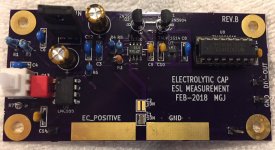
So, I built the little test fixture shown in Figure 2 below. The idea is to create a parallel resonant circuit between the capacitor's ESL, and the test fixture's capacitor C1. We know the value of C1, so if we measure the resonant frequency, we can use it to calculate the value of ESL from simple parallel resonant circuit analysis.
High speed voltage comparator chip U4a, and the noninverting buffer Q1+Q2, create a positive feedback loop. Parallel resonant circuit ESL + C1 create an output voltage, which is amplified by U4a, buffered by Q1+Q1, and fed back to the resonant circuit by resistor R3. With no inversions.
High speed CMOS Schmitt trigger U7 cleans up the not-quite rail-to-rail output of the emitter followers, and presents a full rail-to-rail clock signal to U8, which is configured as a divide-by-1024. This drops the frequency from Megahertz to kilohertz, allowing the test jig to be used even with cheapo $25 DMMs from AliExpress, that have a frequency counter mode.
I built a PCB (Figure 3) and populated C1 but not C2, so the capacitance which resonates with the ESL is 10 nF. {Measured value: 9.49 nF}
When I used the test fixture to measure the inductance of a few fixed inductors I bought from Mouser.com, the measured inductances were within 10-15% of the manufacturer's rating. (Tolerance of the inductors was 5%). See Figure 4. Accuracy is okay but certainly not spectacular.
Trying out the test fixture on a bunch of electrolytic capacitors of various sizes, I got the results shown in Figure 5. A very accurate, very expensive HP5335A 9 digit frequency counter was used to measure the final output frequency, and then a little spreadsheet made the parallel resonant calculations.
Figure 5 seems to show that ESL inductance decreases when capacitor diameter increases. I plotted this and attempted to fit a curve to the measured data, see Figure 6. The fit isn't great.
Since I didn't want to solder and un-solder capacitors to the test fixture every time I made a new measurement, I used wide gold fingers to make contact with the capacitor leads. I'm sure this increases the length of the current-loop, compared to a stuffed and soldered electrolytic cap whose lead-length is probably only 1mm. So I expect that in-circuit ESL is probably less than the value measured by this fixture, perhaps by as much as the inductance of an extra 10mm of total length. But that's the price of quick-connect measuring terminals I suppose.
_
I got interested in this "inductor" mode of operation, and wanted to measure the Equivalent Series Inductance (often abbreviated "ESL") of some big electrolytic capacitors I'm putting in a power supply. Although I've got several test instruments that will measure ESR, none of them are able to measure ESL. Probably because of the much higher frequencies involved; the capacitor in Figure 1 doesn't behave inductively until about a Megahertz.
So, I built the little test fixture shown in Figure 2 below. The idea is to create a parallel resonant circuit between the capacitor's ESL, and the test fixture's capacitor C1. We know the value of C1, so if we measure the resonant frequency, we can use it to calculate the value of ESL from simple parallel resonant circuit analysis.
High speed voltage comparator chip U4a, and the noninverting buffer Q1+Q2, create a positive feedback loop. Parallel resonant circuit ESL + C1 create an output voltage, which is amplified by U4a, buffered by Q1+Q1, and fed back to the resonant circuit by resistor R3. With no inversions.
High speed CMOS Schmitt trigger U7 cleans up the not-quite rail-to-rail output of the emitter followers, and presents a full rail-to-rail clock signal to U8, which is configured as a divide-by-1024. This drops the frequency from Megahertz to kilohertz, allowing the test jig to be used even with cheapo $25 DMMs from AliExpress, that have a frequency counter mode.
I built a PCB (Figure 3) and populated C1 but not C2, so the capacitance which resonates with the ESL is 10 nF. {Measured value: 9.49 nF}
When I used the test fixture to measure the inductance of a few fixed inductors I bought from Mouser.com, the measured inductances were within 10-15% of the manufacturer's rating. (Tolerance of the inductors was 5%). See Figure 4. Accuracy is okay but certainly not spectacular.
Trying out the test fixture on a bunch of electrolytic capacitors of various sizes, I got the results shown in Figure 5. A very accurate, very expensive HP5335A 9 digit frequency counter was used to measure the final output frequency, and then a little spreadsheet made the parallel resonant calculations.
Figure 5 seems to show that ESL inductance decreases when capacitor diameter increases. I plotted this and attempted to fit a curve to the measured data, see Figure 6. The fit isn't great.
Since I didn't want to solder and un-solder capacitors to the test fixture every time I made a new measurement, I used wide gold fingers to make contact with the capacitor leads. I'm sure this increases the length of the current-loop, compared to a stuffed and soldered electrolytic cap whose lead-length is probably only 1mm. So I expect that in-circuit ESL is probably less than the value measured by this fixture, perhaps by as much as the inductance of an extra 10mm of total length. But that's the price of quick-connect measuring terminals I suppose.
_
Attachments


Interesting stuff... FWIIW
Down at the low frequency end of things I had to design an auto-resonance circuit for loudspeakers and ended up with some 4pin power op-amp set up as a current source driving the loudspeaker with voltage/terminal feedback through a CA3080 and some peak detecting circuit to control the bias in the CA3080.
It looks like you are hitting things with the 555 to get stuff going and then the high speed comparator takes over when things are ringing.
The CA3080 is obsolete but just to float a possibly incomplete idea...
Picture.
C1 is your added capacitance. DUT is the one you want to measure. R1 turns U1 into a current source. Q1/Q2/Q3 replace the CA3080. It's one of those gmRL, gm = Ic/26mV or something, things. U2 makes the output single ended for feedback to U1.
Then you need some peak detecting thing to set/limit BIAS such that beautiful sine wave stuff appears.
Apologies in advance.
Attachments

Top effort Mark. Early days no doubt in terms of using the new test set-up.
The first things that come to mind are:
Does the test set up provide a comparison measurement for an axial e-cap with a much higher ESL format part - or would that require C1 change?
Would a series of tests with increasing C1 (C2) value show correlated lowering in resonance frequency, and when would ESR start to be an influence?
Nice little jig, Mark.
Have you tried other types of buffers, to solve the dead-band issue?
Could be a classic monolithic solution, like the OPA633, but I am preferentially thinking of low-cost alternatives, like a number of paralleled 74HCU04 operators (and swapping the + and - inputs of the comparator, of course).
The 74HCU might even be used to provide the gain, too.
Choosing a comparator without built-in hysteresis could also help in this respect
Try this in a transient analysis simulation! I think you'll be pleased. Also run an AC analysis, to observe the Q of the resonant circuit & the steepness of the phase-jump at resonance.Would a series of tests with increasing C1 (C2) value show correlated lowering in resonance frequency, and when would ESR start to be an influence?
You may agree with my assessment, that it's a tradeoff between circuit goodness and the bravery (cojones) of the builder.
... other types of buffers, to solve the dead-band issue?
I have good news for you. You can use just about any waveshape to supply input energy to a high-Q resonator, and still get a well behaved output at the resonant frequency. (This is why Class-C amplifiers work so well in RF circuits.) Even the horrifying "Modified Sinewave" output of a cheaply made 12VDC-to-230VAC inverter, is sufficient. And that has got a dead band wide enough to fit a double decker bus.
You can monkey around with this in simulation, by inserting a voltage source in series with the base(s) or emitter(s) of the followers, to find out how much or how little it affects the oscillation frequency.
I investigated using CMOS inverters to amplify the 200mV P-P worst case input, up to fullrail square waves. But the ones with sufficient GBW (namely SN74AC04) were internally buffered and impossible to bias; while the unbuffered ones (namely, CD4049UB and 4069UB) did not have sufficient GBW. However I didn't try the newest 74AUC2G logic family which runs from 2.0V and is open drain only. It certainly has the GBW but I don't know whether it is internally buffered. I suspect so.
And I don't mind paying $6.15 for a Linear Technology voltage comparator IC, as a thank-you for the free simulator LTSPICE.
_
Attachments

The waveshape doesn't worry me at all, but the dead-band also means a gain of ~0 under quiescent conditions, making the startup of oscillations difficult, if not impossible, which is why you felt the need to include a manual kick-start.I have good news for you. You can use just about any waveshape to supply input energy to a high-Q resonator, and still get a well behaved output at the resonant frequency.
../..
Nothing wrong with this, if it is required and unavoidable, but if it can be avoided, it is probably preferable.
I can easily understand why you chose not to bias the followers, it would be messy and complicated, but if there is no alternative reaction path, the consequence is a non-self-starting oscillator.
The 74AC family is not suited to linear applications, because of the built-in hysteresis on all inputs, including "normal" ones, and regular HC's are buffered thus unstable in linear regime, but 74HCU's might be suitable, for the buffering part at least.
The speed might be marginally low if you aim at tens of MHz, but this has to be tested (they can be pushed to more than 6.5V Vdd if required).
It is just an idea, to improve and streamline a worthwhile project.
If you want to favor LT, you can probably find a (relatively) high current buffer or opamp in their portfolio.
Another possibility would be to statically bias one of the transistors at a few mA, just to keep the reaction path live under quiescent conditions.
As soon as the oscillations start, the symmetrical operation would be restored.
It could be as simple as a resistor tied to Vcc or GND.
It always starts up, thanks to the combination of hysteresis and LPF negative feedback thru R5-C5.
However when the DUT is a ridiculously low Q device like the one in the photo below (4.7uF, ESR=11 ohms(!!)), the circuit doesn't continue to oscillate. Its output squeggs and burps and refuses to behave. I installed the pushbutton + LMC555 on Rev.B, in a desperate attempt to measure ESL of these types of unreasonable capacitors. My pipe-dream idea is to provoke oscillation for a large enough number of cycles that I can capture something on a digital storage scope. No luck yet.
But for reasonable capacitors with reasonable values of ESL & ESR, giving reasonable resonant Q (such as all the ones listed in Figure 5 of post #1), oscillation starts immediately and I never needed to press the button.
Yes those are grains of rice.
Attachments

Thank you, Chris! It was a fun project, even the part where I had to hand-solder an SOT-23-5 surface mount device. Those are small!
Thanks for the clarification, things are clearer now.It always starts up, thanks to the combination of hysteresis and LPF negative feedback thru R5-C5.
However when the DUT is a ridiculously low Q device like the one in the photo below (4.7uF, ESR=11 ohms(!!)), the circuit doesn't continue to oscillate. Its output squeggs and burps and refuses to behave. I installed the pushbutton + LMC555 on Rev.B, in a desperate attempt to measure ESL of these types of unreasonable capacitors. My pipe-dream idea is to provoke oscillation for a large enough number of cycles that I can capture something on a digital storage scope. No luck yet.
But for reasonable capacitors with reasonable values of ESL & ESR, giving reasonable resonant Q (such as all the ones listed in Figure 5 of post #1), oscillation starts immediately and I never needed to press the button.
Yes those are grains of rice.
Even if you manage to sustain or measure oscillations in extreme conditions, I don't think it will help a lot: below a certain Q, the resonant circuit will become mostly a RC circuit, and will not be able to provide 0° the phaseshift required, and the oscillator will simply degenerate into a multivibrator or RC oscillator.
A possible workaround (which I already used in a reactancemeter using similar principles) is to add a small, known inductor in series with the CUT to raise the Q and make oscillations possible, but if the auxiliary L needs to be 10x the measured value, it will probably not be of a great help
I would be pleased to use this little fixture to measure ESL of other diyAudio members' capacitors, at no charge. Just mail them to me and I'll make the measurements. If you want me to send the capacitors back to you, please include return postage in the parcel. PM for address.
Mark Johnson
Mark Johnson
Inductance of a Straight Wire: A Calculator
EDIT- that calculator fails for a 500 foot (150m) wire like my power-line from the street. Calculating 5 feet then multiplying by 100 gives an answer that agrees with wire-table data.
EDIT- that calculator fails for a 500 foot (150m) wire like my power-line from the street. Calculating 5 feet then multiplying by 100 gives an answer that agrees with wire-table data.
Last edited:
I know that it is about 8nH / cm 🙂
But can Mark measure it? From the measuremnt table it looks like
the capacitor inductance is the inductance of the wiring.
But can Mark measure it? From the measuremnt table it looks like
the capacitor inductance is the inductance of the wiring.
Yes, it is generally reckoned that the inductance of a capacitor is roughly equal to the inductance of a wire in the same place. In most cases this is dominated by the wiring to the capacitor, not the component itself.
The method is somewhat flawed. No sacrifices to the God LT please.
An electrolytic capacitor has the following LCR elements:
- Inductance of connections. This mostly follows the rule for short wires "~1nH per mm". Resistance of connections.
- Distributed capacitance, distributed inductance, distributed resistance.
"Distributed" implies that effective capacitance at HF is lower, in the same proportion effective inductance is lower. Nominal capacitance value is useless at HF. Most trouble in practical applications comes from inductance of connections, as the distributed LCR is self-damped, low Q.
Of more interest is to measure square-wave response of paralleled capacitors, like electrolytics with compact short-lead film or ceramic, then deriving a circuit with similar square wave response. PCB layout techniques for paralleled capacitors are explored in the same way.
... measure square-wave response of paralleled capacitors, like electrolytics with compact short-lead film or ceramic, then deriving a circuit with similar square wave response.
Please do! DiyAudio members would love to know what you found out.

- Status
- Not open for further replies.
- Home
- Amplifiers
- Power Supplies
- Measuring the "ESL" inductance of electrolytic caps (at 10 MHz!)