A friend of me receive a device of this model in not working condition - made around the late 70th.
under
https://www.diyaudio.com/community/threads/michaelson-austin-tva-10.14116
was mentioned various deficiencies in the circuit design of one of the old versions under
http://www.papworthaudio.co.uk/tva10spc.html
(image under http://www.papworthaudio.co.uk/other.html)
- consequence is an unwanted oscillation (stability issues) under certain conditions.
Bevor I start replacements and troubleshooting on his device, I want to know, if there descriptions for upgrades in the circuit design so that this unwanted oscillations is no longer present.
I guess that was taken into account accordingly in the circuit of the current version under
http://www.papworthaudio.co.uk/redrange.html
Who can upload this associated circuit diagram ?
How many different versions are exist at whole of the TVA-10 and which of them shows the above mentioned deficiencies in the circuit design ?
Thanks for any advices in advance.
According the attached images there are a version with two capacitors and a version with four capacitors behind the rectifier
Additional a version without PCB and a version with PCB (main board) for input and driver stage
The version with PCB exist with two different input and driver tube configurations (3x2 and 2x3 lines) and thus two different PCB layouts
As I know, all versions have partridge-transformers and the McIntosh Unity coupled circuit in use - very important for a tight and clean bass character.
Already exist and closed threads concerning the Papworth predecessors (all devices actually integrated amps with volume control on back panel, but without input selector):
https://www.diyaudio.com/community/threads/series-heated-tubes.369465/ (Serial heated tubes)
https://www.diyaudio.com/community/threads/michaelson-austin-save-attempt.281302/ (DC resistances transformer winding)
https://www.diyaudio.com/community/threads/capacitor-choice-for-attached-schematic.95266/ (capacitors)
More URLs
https://www.audiogon.com/listings/michaelson-and-austin-tva-10-el34-amp-tim-de-paravicini
https://www.diyaudio.com/community/threads/partridge-transformers-vs-hammond.245112/
https://www.diyaudio.com/community/threads/partridge-transformers.183269/
Output transformer of TVA-10 operates according this: McIntosh Unity coupled circuit
https://www.mennovanderveen.nl/imag...018-11-09_VDV-2100-CFB__CFBH-applications.pdf
https://www.diyaudio.com/community/threads/unity-coupled-circuit-amplifier.111673/
https://audiokarma.org/forums/index...mcintoshs-unity-coupled-circuit-works.569405/
https://www.jogis-roehrenbude.de/Leserbriefe/Alexander-Linden-EL84-Amp/Amp.htm
Attachments
-
 TVA-10 top cover-I.jpg88.9 KB · Views: 239
 -
 TVA-10 top cover-II.jpg21 KB · Views: 208
 -
 TVA-10 top cover-III.jpg74.7 KB · Views: 211
 -
 TVA-10 top cover-IV.jpg71.2 KB · Views: 187
 -
 TVA-10 top cover-V.jpg53.5 KB · Views: 197
 -
 TVA-10 top cover-VI.jpg199.6 KB · Views: 190
 -
 TVA-10 top cover-VII.jpg236.2 KB · Views: 207
 -
 TVA-10 top cover-VIII.jpg68.6 KB · Views: 187
 -
 TVA-10 botton view.jpg222.9 KB · Views: 176
 -
 tva10 front volume contr..jpg13.9 KB · Views: 188
 -
 tva-10 Papworth.jpg15 KB · Views: 250
 -
 TVA-10 schematic-II.gif39.9 KB · Views: 320
 -
 TVA-10 schematic.PNG156.9 KB · Views: 350
 -
 TVA-10 top cover-IIa.jpg25.3 KB · Views: 291
Last edited:
TVA-10 versions without top cover
Attachments
-
 TVA-10 without top cover-VII.jpg437.4 KB · Views: 109
 -
 TVA-10 without top cover-VIII.jpg169.7 KB · Views: 97
 -
 TVA-10 without top cover-IV.jpg179.1 KB · Views: 97
 -
 TVA-10 without top cover-III.jpg175.9 KB · Views: 94
 -
 TVA-10 without top cover-II.jpg188.7 KB · Views: 103
 -
 TVA-10 without top cover-I.jpg167.4 KB · Views: 100
 -
 TVA-10 without top cover-V.jpg187.3 KB · Views: 116
 -
 TVA-10 without top cover-VI.jpg212.9 KB · Views: 109
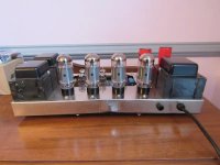
Who knew there were that many versions. I have a TVA-10, a 2 cap version, but mine is different on the top of the chassis. There is a black metal plate that fits down over the 12xx7 tubes and covers the circuit board.
Mine works fine, after I grounded it properly and eliminated the hum. The bias circuit needs improving.
Mine works fine, after I grounded it properly and eliminated the hum. The bias circuit needs improving.
most important is a individual bias adjustment for each tube - so I think. Otherwise an exact matched quad set of output tubes is absolutely necesary.
P.S.: What happens with Papworth Audio ?
email address "eddy@papworthaudio.demon.co.uk" don't longer exist.
P.S.: What happens with Papworth Audio ?
email address "eddy@papworthaudio.demon.co.uk" don't longer exist.
Two matched pairs would suffice. But an individual bias adjust option per tube would be even better.
Btw, is this a Tim de Paravicini design?
Best regards!
Btw, is this a Tim de Paravicini design?
Best regards!
- Home
- Amplifiers
- Tubes / Valves
- Michaelson & Austin's TVA-10 vs. Papworth's TVA10 (Burgundy Range) - Schematic Differences ?