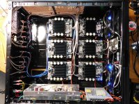
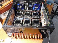
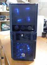
It's too cold in the garage to work with resins, so it's an opportunity to repackage my amplifier. I used an old mid tower PC case that was about the right size. I needed a few pieces of sheet metal.
There are 6 channels powered using a 150W @24VDC supply. This provides ~35W into 8R load for tweeters and midranges, These channels have input attenuators to match driver sensitivity differences.
There are 4 channels powered using a 320W @36VDc supply. This provides ~80W into 8R load and 160W into a 4R load for woofers and subwoofer.
Two cooling fans, with analog fan speed control (0-max) for cooling. I actually use very little amplifier power and I run them slow enough to see them turn.
Attachments
Starting to look really good, Don!The WN_SEL_425_A4 with a horn stand and the DE75TN driver.
Pic#3 shows the FR effects of various lower cutoff freqs [300,350,400,500Hz]. It's possible to cross lower than 500Hz with this driver and horn.
Still interested in aluminium, with coating?

That's correct, the DE75TN fades at 8-9Khz like most of the 2" CDs. The alternative would be a coax CD but they're still expensive. This is an easy way to get the last octave clean (for me that's 7-14Khz)
I'm not convinced the coax drivers are significantly better, apart from extra output in the top octave.
However, this is the old DE75, without TN (soft suspension).


Last edited:
Thanks. Those DE75 curves look like it's diaphragm won't go low enough, unless its been limited by the test horn. I've also done some experiments with the last octave and I notice if it's missing or power mismatched, but it's quality it not as important. So I'm still not motivated to get a coax driver.
The DE75TN actually covers a wide enough band for my midrange. I would like to try the aftermarket poly edge and aluminum diaphragms at some time. However my next steps are building the WN270 horn.
The DE75TN actually covers a wide enough band for my midrange. I would like to try the aftermarket poly edge and aluminum diaphragms at some time. However my next steps are building the WN270 horn.
Amplifier background noise
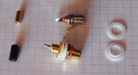
When I repackaged my Amplifier, I also added another SMPS, 2 more amplifier boards, and a metal case. The amplifier background noise increased to an unacceptable level so I went looking for the cause(s). The background noise sounds like a combination of broadband hiss and some variable antennae action. I've listed the 3 fixes and a pic of the parts changed. A relatively easy fix.
Fix#1 : the RCA jacks where non-isolated, so the signal return terminated to chassis. All RCA jacks were replaced by isolated versions and the noise decreased, but still not good enough.
Fix#2 : the amplifier boards mounting holes are also plated and connected to gnd within the PCB. I had metal standoffs that created a return connection to chassis (ground loop). All amplifier board standoffs were replaced with nylon standoffs to break this connection. The background noise decreased some more, but still not good enough.
Fix#3 : three amplifier boards each have input attenuators controlled by a digital 2 bit rotary encoder. The case of the encoder is connected to signal ground and when installed connected to chassis ground (another ground loop). The rotary encoders were isolated using nylon collar+washer. Now the background noise is low enough to be acceptable.
When only the amplifier is powered on, and I place my ear close to the drivers, the woofers+sub are silent and the MF+HF amplifiers have a little noise (faint). The difference could be from either the CD's higher sensitivity or the input attenuators on my MF+HF amplifiers. Turning on the PC (Xonar card) raises the background noise a very small amount. I don't hear background noise at my normal listening position anymore. The 2 SMPS cases are internally connected to power gnd, and the chassis is connected to AC safety gnd.
Attachments
great detective work Don. On the one hand, I can't help but think you should have known better in the first place. On the other hand, unlike shying away from any amp w/o balanced inputs like I do, you've found what it takes to make unbalanced work well enough and saved yourself a fair amount of $
where would be my best bet for learning to set up a crossover like this with eqapo I have the programme I just can't get my head around itSound card Xonar AE, S/W DSP
I wanted to integrate a few pieces of equipment for playback, testing, server and making configuration(s) changes a little easier.
I have an old PC (MN2-SLI deluxe MB, Phenom9850, circa 2008) lying around and decided to repurpose it. Windows10 can be installed without a licence and it has an optional "compatibilty pkg" for older H/W that worked perfectly. I even installed the SoundMax Vista audio drivers for the on board soundcard. Then I added an ASUS Xonar AE Pci card, installed EqAPO, Rephase, REW, and Spotify. The PC has flexible fan control so it can be made fairly quiet as well. The PC (bare) is placed beside the amp to minimize ground loops, using short audio cables, and accessed via RDP. Time for s/w DSP.
The Xonar has 3 different DACs, ESS ES9023 (headphones), Cirrus CS4245 (R,L), and Cirrus CS4361 (RR,RL,C,S,SR,SL). The A/D has a HP filter that can be disabled (datasheet) but there does not seem to be a windows control for it. Usually the input A/D is the weakest link in a loopback test. Sound wise I don't hear the difference between the min phase and linear phase but I'm still playing with it. It also sounds comparable to my active analog XO. The PC load is 12% total for 8 x 8K taps x 32bit FIR at 44.1KHz playing Spotify. The PC load is only 8% for the IIR filters.
Pic#1 - loopback THD for ES9023
Pic#2 - loopback THD for CS4245
Pic#3 - loopback THD for CS4361
Pic#4 - Equalizer APO used to implement min phase IIR filter XO, and ideal templates
Pic#5 - Equalizer APO used to implement convolution FIR based linear phase filter XO, and ideal templates
Usually with an example and a few pointers to where the important things are located.
I've attached a stripped version of the config files I use for IIR XO filters. There is a good EAPO help (reference) file and a tutorial link included in the
Windows Program Start Equalizer APO folder. EAPO can do alot, if you need more help with the settings or something specific, feel free to PM me.
A few key items.
1) the program installs at "C:\Program Files\EqualizerAPO" and there is a key default configuration file at subfolder "\config\config.txt".
2) I'm assuming you will use the "configuration editor" to graphically edit and view configurations, but you can also edit in a text editor
2) the program always reads "\config\config.txt" first, so I also place the other configuration files that subfolder
3) since we're always trying configurations, I "include" the actual configuration setup(s) in the "config.txt" file.
4) at the top right of the EAPO window you can select the soundcard and output channels (stereo, 5.1, 7.1, etc)
5) at the bottom of the EAPO window is an analysis window, select the channel and it will show the net processing for that channel.
I strongly recommend that you initially test each output channel using a low cost fullrange or a woofer.
Attachments
Last edited:
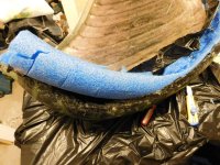
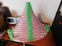
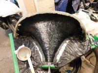
These pics are the WN_SEL_425_A4 made in fiberglass composite. The bare fiberglass horn is 1.5Kg and the CLD (rubber and plaster) increase that to 5.9Kg (wet) that should reduce to total 4.5Kg (cured). It's about the same mass as my DE75TN driver.
Hopefully these pics stay in the right order. [EDIT] the pic order is scrambled again , new pic# in brackets), anyone know how to fix this ?
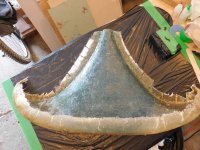
pic#1 (1) - horn plug mold (1/2 symmetry, R22mm RO added, 57cmx38cm) with skins curing in the sun
pic#2 (8 )- the 4 skins that I need for 2 horns
pic#3 (7 )- gluing the horn halfs together
pic#4 (6) - flash trimmed and wood stiffeners added (it's now about stiffness of an ABS horn)
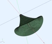
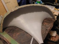
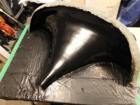
pic#5 (5 )- trying a translucent horn, but I would like more damping and stiffness
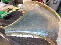
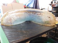
pic#6 (4) - CLD composite, layer silicone rubber 2-3mm thick + sand dusting for the next layer
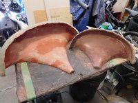
pic#7 (3) - CLD composite, layer plaster of paris 1-2cm thick, poured into pockets
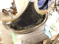
pic#8 (2) - CLD complete, ready for intial tests, before any finishing (filler+sanding+paint)
@DonVK, I'm exploring options to dampen my horn.
- Can I confirm that you first applied silicone on the fibreglass and then used POP? Does it adhere well?
- Initially, I intended to apply POP directly on the horn, but I realised that once it solidifies, it shrinks a bit and doesn't adhere well to PLA or fibreglass. Is my understanding correct?
The silicone will bond directly to the fiberglass very well, but you would need to check this on your base material (PLA ?) Clean and dry sand was poured over the wet silicone and very lightly pressed into the surface, Then the excess sand was shaken off. The sand layer is important as it forms a rough surface layer that the plaster will bond to.
The plaster is non-shrinking from DAP Product Page and it's sold in 25lb bags. I added stiffening braces to the fiberglass that also provided "pockets" to pour the POP into. There was no detectable shrinkage. The product will set solid in 30min (or less) but it will take a few days to cure to full strength (depending on thickness).
The plaster is non-shrinking from DAP Product Page and it's sold in 25lb bags. I added stiffening braces to the fiberglass that also provided "pockets" to pour the POP into. There was no detectable shrinkage. The product will set solid in 30min (or less) but it will take a few days to cure to full strength (depending on thickness).
WN270 Roundover Added
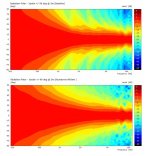
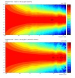
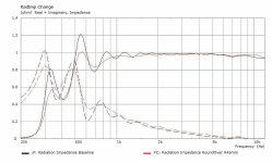
A generous round over was added for reducing mouth diffraction, improving the termination to 4Pi space and provide a mounting surface for a small tweeter (>6Khz). The base horn was ~65cm wide, and with an R45mm roundover, the horn now becomes 83cm wide. This is a comparison of the effect of adding this R45mm roundover before the build.
The basic nature of the horn stayed the same with the usual improvements expected from roundovers. The horn mouth becomes larger so it controls the wavefront better at lower freq. The mouth termination is more gradual and dampens the radiation impedance curve ripples. The vertical polar is smoothed the most because it had a more acute mouth angle than the horizontal. The roundover is constant radius because its easier to for me to build. A variable radius would be marginally better, however this is already at the point of diminishing return.
Attachments
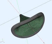
WN270 Mold
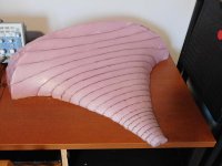
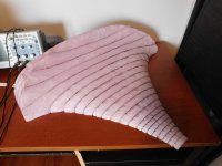
This is the second fiberglass mold, and its created in a similar fashion to the first WN425 mold. The CAD mold was shrunk 3mm, sliced into standard XPS width slices, cross sections printed on paper, hot wire cut XPS slices, then glued together. Then lots of finishing work and contour checks.
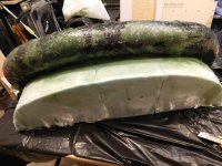
The side-side comparison to the WN425 mold show how much larger the WN270 horn is.
Attachments
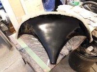
WN270 First Skin
The mold was waxed and costed in PVA release compond. However the first skin stuck to the mold in a few places in the roundover. I suspect the high humidity did not allow something (eg. primer, paint, wax, PVA) to fully dry and it did cause some minor surface damage to the mold. So I'll be waiting a few says for drier weather to refinish the mold surface.
A few pics of the molding process and the first skin pulled from the mold. It required 0.5L resin and 0.6m3 of fiberglass. It looks a bit 2 tone because I started with leftover resin (blue tint at throat) and finished with new resin (orange tint at roundover). It still needs to have the edges trimmed.
Attachments
This is clever!The silicone will bond directly to the fiberglass very well, but you would need to check this on your base material (PLA ?) Clean and dry sand was poured over the wet silicone and very lightly pressed into the surface, Then the excess sand was shaken off. The sand layer is important as it forms a rough surface layer that the plaster will bond to.
I do not have silicone at hand, but I do have resin which I could mix with French chalk to thicken it for thick paste/putty-like consistency and follow a similar method. Thanks for this!
- Home
- Loudspeakers
- Multi-Way
- Modular active 3 way - work in progress