Hi all,
Thanks for all of your feedback. Based on your inspirations and shown directions i tried to do some investigstion too. I searched the ltc6090. There is a guy who built roughly ( or at least) 70 amplifier projects lme49811 and ltc6090 too and also discrete ones. I asked him for a suggestion. I will share the result. His site anyway is BuildAudioAmps. worth to have a look. Impressive work.
I found another site where several circuit considerations can be found . it starts with single ended circuits. Current source and and one output stage mosfet with different driver stages (transistors, tube, fet or Opa). The site is V-to-I Amplifers. (Opa circuit uploded - i dont like inthis format- close to rail operation of Opa. ) If i can find further result i will share. Currently for me the high voltage opa driven class ab or the single ended simple circuits are simphatic. I will share my selection and built experiences at the end.
Attachments

Szia,
you have asked for FET + opa, here is one more straightforward option to play with.
Персональный сайт - УМЗЧ на полевиках мосфит IRFP 9240, IRFP 240
I never built this, but SPICE sym works fine as expected. By swapping TL071 for a OPA1612 you get extreme low THD, so limit shall be the implementation at al.
The trick here is that the transistor section already has a gain >>1 set by R10/14 and R11/15 so you can run the OPA at low supply and output.
If you are not stick to FET power stage then you may look at here as well Taming the LM3886 Chip Amplifier
Endre
Last edited:
This is an awfull trick.gain >>1 set by R10/14 and R11/15 so you can run the OPA at low supply and output
It clubbers THD. See with LTSpice.
Thermal stability is terrible. Output stage is prone to thermal runaway.
This is an awfull trick.
It clubbers THD. See with LTSpice.
Thermal stability is terrible. Output stage is prone to thermal runaway.
I used TINA with a slightly modded ckt, I decreased gain to 8 and swapped BD parts for faster. I got < 0.3% THD for the output stage at various signal levels and load. When I applied OPA1612 THD vanished due to its huge open loop gain as schoolbook suggests.
Thanks that you mentioned thermal things, I check this !
But you must realize that the bootstrap voltage creates a huge common mode voltage on the +/- inputs. So there is a limit on how much voltage swing you can add. The chip rails can never become reverse polarity wrt the inputs, ie the negative rail max is a bit below zero volts and the positive rail minimum is a bit above zero volts.
Sorry, I don’t quite follow. Here is a simple bootstrapped NJM5534D with +/-44v rails driving an 70Vpp output. Gain was about 28dB and the input was just a function generator with 2.7Vpp input. What huge common mode voltage are you referring to? This is a dual rail circuit referenced to true 0v GND. The output stage MOSFETs would use the the same rails.
Circuit based on this 1974 article by Surjan Dogran:

Last edited:

It is very difficult to achieve 50-100 watts with SE class A . If you would, you will not need OPA at all .
Last edited:
Yes you right made a quick calc and see it is 200 250w power dissipatio. Per channel.
So maybe I have to reconsider. And meanwhile I read an article which describes that the switching mosfet application in these simplified zen amplifiers results terrible distorsions because of the nonlinearity and the lack of feedback.
So again im far from the original goal a really simple good soundong amplifier witbout kW dissipation.
Here is a nice, proven SE Class A amp that is 50w. Built in cap multiplier PSU and SSR DC protection circuit.
Based on the Alpha BB amp from this thread:
Aksa Lender P-mos Hybrid Aleph (ALPHA) Amplifier
The Alpha Big Boy with Buttah (ABBB) 52w Class A Amp GB
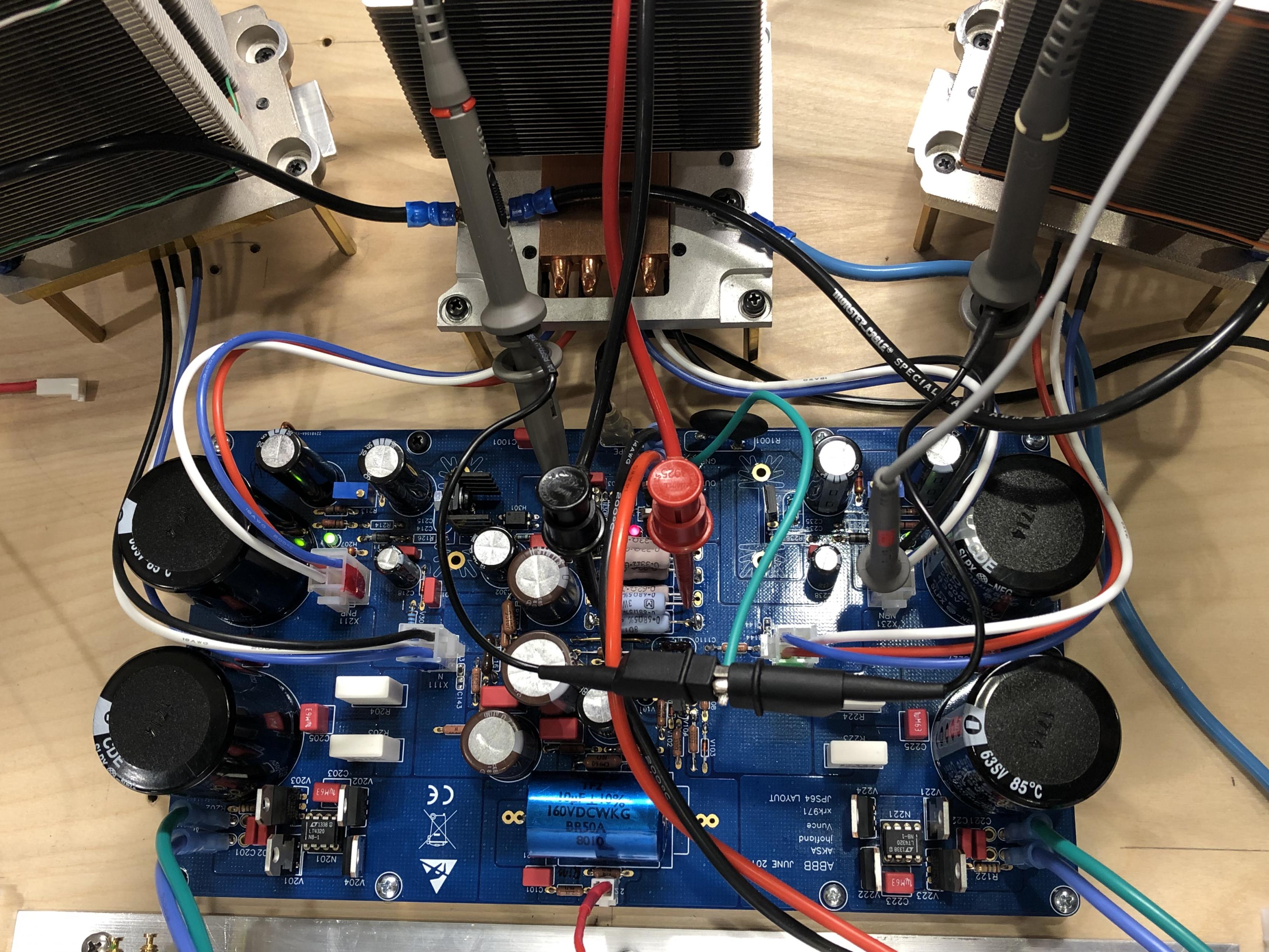
Large thermal dissipations are handled with CPU coolers and quiet Noctua fans.
Based on the Alpha BB amp from this thread:
Aksa Lender P-mos Hybrid Aleph (ALPHA) Amplifier
The Alpha Big Boy with Buttah (ABBB) 52w Class A Amp GB
Large thermal dissipations are handled with CPU coolers and quiet Noctua fans.
Last edited:

Yes you right made a quick calc and see it is 200 250w power dissipatio. Per channel.
At least. A room heater you can't switch off in summer.
Yes ;-).
Unfortunately or fortunately i bought lower voltage toroids (17V AC ) plus the active ripple filtering (cap multiplier) eats some volts too, so at the end the useful power is max 20W but the heating capacity is all together 300W. The bridge cooling was a surprise - i will replace soon since they are quite hot(65C) the other parts are 50C. Even the toroids are around 30-35C in spite of being 200VA each.
Scematics is similar to that
PASS LABS CLONE - ALEPH 3 Amplifier KK-PCB
I received the double DC protection boards, so soon it will be completely dual mono. Currently only this part is common.
I will finish soon an active preamp (20dB.). So soon a completed set is ready. Only the boxng.....
You can wind yourself extra turns on the toroid to adjust required voltage . All you need is some wire .
Rise the heatsinks and the fans with 2-3cm up from the base board. Your cooling will be much better. 60-70C is fine for the rectifier bridge, as most of them are specified for 90-100C.
Anyway, the air can cool down the rectifier, and the transformers once You will put the amplifier into a box. Just let the air in on the front, and out on the top, and bottom.
Sajti
Anyway, the air can cool down the rectifier, and the transformers once You will put the amplifier into a box. Just let the air in on the front, and out on the top, and bottom.
Sajti
Last edited:
Yes i was considering the rising of the boards heatsinks, just havent found the stable and safe way- anyway thanks for reminding. Regarding the bridge i wanted to keep far the ac parts from the board as much as possible. Maybe in a box an air channel as you sggested will be.Rise the heatsinks and the fans with 2-3cm up from the base board. Your cooling will be much better. 60-70C is fine for the rectifier bridge, as most of the are specified for 90-100C.
Anyway, the air can cool down the rectifier, and the transformers once You will put the amplifier into a box. Just let the air in on the front, and out on the top, and bottom.
Sajti


- Home
- Amplifiers
- Solid State
- MOSFET Audiophile amplifier with OPA driver???