The PS caps need to be at least 500V rated, as the B+ will rise over 500V on startup with the edcor PS transformer when the tubes are cold.
360V x 2 x sqrt 2=507V with no current flowing.
The 500V Panasonic TS-UPs have a surge rating of 550V. Allied sells 500V Cornell Dublier Caps and there are also JJ's and a few others. The coupling caps also need to be rated higher than 500V for the same reason, so 600-630V parts are the way to go here, and that's what's shown.
If you ask folks what they recommend for coupling caps, you'll get almost as many opinions as you get responses. Good value/sound ratio seems to be russian 600V teflon via ebay and 600V Auricaps, but that's just one opinion among zillions.
I'd use wirewound R's in the PS; look at the current through them and the voltage drop across them, use ohm's law, and be sure to spec the R's with 2X or more margin or they will get hot!
The PS parts spec'd can be substituted with other parts, just keep in mind voltage and power requirements. A larger choke certainly wouldn't hurt, although the dropping R's may have to be adjusted depending on the new choke's R.
I think it's important that the items listed on the BoM be readily available at a reputable vendor (ie. not eBay only). I also think it's a good idea to list lower priced parts and highlight them as being optionally upgradeable. (I personally don't want to offer or hear component opinions.)
For example, the coupling cap spec will be 0.47uF/600V and the 'example' part can be Solen Fast Caps or Xicon Polypropylene at a couple bucks each, and people can replace those with whichever $400 vintage moon dust impregnated, Uzbekistani organic panther spleen oil soaked carbon nanotube interlaced film & foil space ship run caps they prefer.
Who me? Cynical?
..Todd
I think it's important that the items listed on the BoM be readily available at a reputable vendor (ie. not eBay only). I also think it's a good idea to list lower priced parts and highlight them as being optionally upgradeable. (I personally don't want to offer or hear component opinions.)
For example, the coupling cap spec will be 0.47uF/600V and the 'example' part can be Solen Fast Caps or Xicon Polypropylene at a couple bucks each, and people can replace those with whichever $400 vintage moon dust impregnated, Uzbekistani organic panther spleen oil soaked carbon nanotube interlaced film & foil space ship run caps they prefer.
Who me? Cynical?
..Todd
I agree that "boutique" caps. are totally unnecessary in amp with a GNFB loop. However, the Physics of the situation suggest film and foil construction. The idea is to obtain a small error correction signal, which is something I regard as being highly desirable. 400 WVDC 716P series Orange Drops meet the need, at "reasonable" cost.
BTW, Xicon metalized PP parts have steel leads. Use 'em only if funds are all but non-existant.
If 400V caps are okay, then 716P Orange Drops are definitely the ones to start with. But their value doesn't get that high for 600V, I went looking for them earlier.
..Todd
..Todd
Last edited:
I guess I'll put the BJT CCS back under the 12AT7. I'm not ready to start designing tube circuitry yet, and nobody is chiming in with a current regulator diagram.
The only downside to the BJT CCS (that I'm aware of) is that it's less P2P wiring friendly than the current regulator. But a small vero board will simplify that I suppose.
..Todd
The only downside to the BJT CCS (that I'm aware of) is that it's less P2P wiring friendly than the current regulator. But a small vero board will simplify that I suppose.
..Todd
Last edited:
Hi TubeMack,
It's easy enough to omit.
It's probably there (I'm guessing) because the input sensitivity and impedance is such that that amp works fine with a 'passive preamp'; a volume pot, or stepped attenuator.
It can be drawn in as an option to leave or omit. I'd like to hear from the gurus how the pot is affecting the input impedance (or not) and input filter network.
I would prefer to use a passive attenuator rather than a preamp, if the amp is happy running that way.
..Todd
Last edited:
If 400V caps are okay, then 716P Orange Drops are definitely the ones to start with. But their value doesn't get that high for 600V, I went looking for them earlier.
..Todd
You don't need 600 WVDC parts to couple the LTP to the "finals". 400 WVDC should do. The "ideal" 'T7 conditions are 200 to 220 V. on the plate and an IB of 3 mA. Allowing for -50 V. at a KT88 grid adds up to 270 V., which still leaves plenty of rating headroom. Also, take momentary surge handling capability into account. Yet another factor is the few second B+ rise delay introduced by the CL150.
If a 630 VWDC part will give you "a warm and fuzzy feeling", look here. Those SCR France made parts are still under $10 each and they are incrementally better than ODs. Those parts are likely available under the Axon and Solen labels too. Buy where you get the best deal.
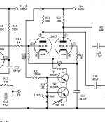
Here's an updated schematic. It's no different than the original circuit, it just has the power supply added to it.
I've added another section to the power supply for the heaters and the CCS power. I don't know if the CCS supply needs better filtering. If so, let me know what to add/change.
There are a bunch of question marks still (FB component values, mains fuse size for example). Please provide answers if you have them.
TubeMack, I'll create a separate call out to show how to wire the input without the pot.
Again, let me know what needs changing. I'm no electronics whiz.
..Todd
Attachments
Dumb question (which might have come up earlier in the thread, if so, my apologies): why not lose the -7.5V supply, return the CCS to ground, make R20 about 270k, and bring R20 up to the B+? That will reduce the parts count and make the current through the LED more constant. That also allows you to bias up the heaters to +50-75V, which will reduce heater-to-cathode voltage on the 12AT7 and potentially reduce noise.
That sounds wonderful to me. I'm not clear on how that's wired...
Just move the power connection to ground, then change R20 to 270 and send it up to the 460v B+? That's it? (and lose its rectifier circuit obviously).
see attached..
..Todd
Just move the power connection to ground, then change R20 to 270 and send it up to the 460v B+? That's it? (and lose its rectifier circuit obviously).
see attached..
..Todd
Attachments
Last edited:
The heaters can run off AC. A center-tapped transformer would be ideal- set up a divider string from B+ to ground, sized to pass a couple milliamps. Tap the string at (say) 60V, bypass that to ground, then connect the heater transformer centertap to the 60V point.
You'll also want to have some 0u01-0u1 ceramic disc caps (600V or more) from each heater pin to the chassis- this will reduce a lot of common-mode HF line noise that will happily couple through the transformer into the tubes.
You'll also want to have some 0u01-0u1 ceramic disc caps (600V or more) from each heater pin to the chassis- this will reduce a lot of common-mode HF line noise that will happily couple through the transformer into the tubes.
The heaters can run off AC.
Already are. The rectifier was just for the CCS supply. The transformer has a 6.3v winding. You definitely lost me with the rest of that.
..Todd
edit- just like your diagram, yes.
Okay. Thanks. I'll add that into the next revision.
..Todd
Already are. The rectifier was just for the CCS supply. The transformer has a 6.3v winding. You definitely lost me with the rest of that.
..Todd
Your diagram is showing the heaters running off of AC, but the center tap of the 6.3V winding isn't grounded......
Sy is suggesting biasing the 6.3V heater voltage of the 12AT7 up to 60 V or so. This is done by a simple 2 resistor voltage divider from B+ to ground that will pass a couple of ma, and connecting the CT of the filament winding between the R's, so the 6.3v heater is referenced to 60v instead of ground.
Last edited:
- Home
- Amplifiers
- Tubes / Valves
- Mullard 5-20 KT88 PP blocks!