That's why I suggested trying it and seeing vs general dogma.. In future I may try it.. people rave over Panasonic PPs but I found them dark and lacking in the design - my opinion vs the web. Pretty much any cap will be better than the old cooked 20+year old Jamicons MF stuffed their amps with at this stage (from bitter experience with my MF A220).So regardless of opinions of those that haven't tried it(makes you wonder) and what can be read on the web
I agree. However (tongue in cheek) that's a large part of the MF sound. I'm tempted to try out a replacement but for now the CDP is possibly a target replacing the 1-bit 1996-7 era DAC..BTW the cause of the preamp not to perform as it should is the choice of opamps. MC33079 is mediocre at best. You could have tried out OPA4134....
You could add nice polyester caps and/or replace the now cooked Jamicon alu electroltyics with some nice organic low ESR on the MC33079/replacement decoupling and the power supply (I suspect it would not have changed between the other amps at that time).
I would be interested in understanding more (objective testing papers) on polyester - I have read that they have a higher residual charge than PP when measured using test equipment but unless that in a phono network or other low noise use case, I suspect polyester doesn't matter too much other than perhaps a difference in sound (another comment from decware - but I'm unsure if that's simply them selling a lower cost part to boost profit or not). In the end it's your amp, your soldering iron and your bank balance. Try, or try not young Skywalker..
Last edited:
I meant Wima MKS so I wrote Wima MKS. They are way better than the electrolytic caps they replace (and often also their modern replacements) and if one wants the crème de la crème for coupling purposes that would be no cap as practically no other film cap will fit in 5 mm pitch. Or one should be willing to "do just something" and use melt glue and flying antenna wires (and open new threads regarding the newly occurred issues ).
In short: the opamp and the caps more for less determine the sound quality in these devices as OP already found out (and bypassed the section because of that). The caps are worn out and B quality so they need replacement anyway. Back to the original but updated/overhauled circuit is best I guess. I would add an RC filter in each input with -3dB point at 100 kHz.
).In short: the opamp and the caps more for less determine the sound quality in these devices as OP already found out (and bypassed the section because of that). The caps are worn out and B quality so they need replacement anyway. Back to the original but updated/overhauled circuit is best I guess. I would add an RC filter in each input with -3dB point at 100 kHz.
Last edited:
Back to the original but updated/overhauled circuit is best I guess. I would add an RC filter in each input with -3dB point at 100 kHz.
Leave out C55 and decouple the power amp from the pre then feed the preamp output in through the pre-out (now decoupled from the power amp). Then add an RC filter to on the power amp input to reduce any RF noise. That could be done changing the value C4 on the power amp schematic next to TR1. If I read that correctly.
Quite like this site for designing RC filters: http://sim.okawa-denshi.jp/en/CRlowkeisan.htm
Yes leave away C55/C155 (use jumper wires) when using it with the power amplifier as 2 caps in series won't make the world any better. There were no GND reference resistors, did you notice? Resistor values in the preamp are also highish values but let's not make it more complicated for now.
That website is good for its purpose, I use it a lot.
BTW there IS a RC filter at the power amplifiers inputs (good) but not at the preamps inputs (not good). I read on the web that it would be good to include those but I never tried it Just joking.
That website is good for its purpose, I use it a lot.
BTW there IS a RC filter at the power amplifiers inputs (good) but not at the preamps inputs (not good). I read on the web that it would be good to include those but I never tried it
Just joking.
Last edited:
The DAC is an ifi iDSD black label. It's RCA out impedance is on the high side at 200 ohms.
This highish output impedance will interact very nicely with C55 and R59 to give a low pass filter as I previously stated so leave C55 and C155 out so that the outputs of IC2 remain disconnected , it will not damage IC2 . I assume the exbass switch only affects the headphone outputs (this was just another thought)
The xbass switch does work on both headphone and line out RCA jacks. Interestingly, with C55 and C155 removed and C3 bypassed (direct coupled), with the xbass on, the low end response was very similar to when all caps were in place with the xbass switched off. So as you spoke of, there must have been a subtle filter network created in those caps and resistors between IC1 and TR1, in addition to TR1's bias being affected.This highish output impedance will interact very nicely with C55 and R59 to give a low pass filter as I previously stated so leave C55 and C155 out so that the outputs of IC2 remain disconnected , it will not damage IC2 . I assume the exbass switch only affects the headphone outputs (this was just another thought)
Thanks to everyone who opined to this post. I did install Wima MKS in C3 & 103 positions, and am pleasantly surprised by how good these inexpensive caps sound over the stock NP electrolytics. Indeed that high DAC out impedance imparted a very noticeable bass boost if just inserted into the preamp out RCA jacks. As was also mentioned, that combination of DAC and preamp did induce a low pass filter which rolled off the highs a bit, and the overall presentation was just too veiled and dark for my ears. So I installed jumper pins on the PC board by lifting one leg of R59 & 159, this separated per-out and amp in to resolve these issues. Severing the peamp section did the trick to flatten out the frequency response and restore lost dynamics. Why the manufacturer did not install preout/main in jumpers on the back panel as so many others do I have no clue.
Please keep this in mind and be surprised how many state that MKS is bad, Wima is bad etc. Even in this thread it was said.I did install Wima MKS in C3 & 103 positions, and am pleasantly surprised by how good these inexpensive caps sound over the stock NP electrolytics.
It is plain nonsense, it is added useless noise: they are better than electrolytic caps and datasheets and measurements are clear on this. Using matchbox sized polypropylene caps with flying lead wires will generally not give better results (certainly not in class D amplifiers).
Last edited:
I used Audio Note Kaisei NON-POLAR PET Electrolytic Capacitor 10uF 350v, bypassed with EPCOS B32529D6104J 0.1uF films to replace C55, C155 and all the remaining non-polar Jamicons. The do make a very noticeable difference.Those Wima MKS are better than the average electrolytic cap and you don't need to replace them in the future. ...
So regardless of opinions of those that haven't tried it
I hope the MKS or Nichicon Muse ES return similar results.
You are a harsh judge jean-paul given the MC33079P is a 20+ year old design!BTW the cause of the preamp not to perform as it should is the choice of opamps. MC33079 is mediocre at best. You could have tried out OPA4134....
...
For the time it is a low noise quad op-amp device with decent characteristics.If you are going to look at alternatives, cut to the chase and obtain a pair of Sonic Imagery Labs Model 994Enh-Ticha Dual discrete op-amps. With suitable decoupling - I'd highly recommend replacing C52 & C53 with KEMET T350M107J020AT solid tantalum 100uF 20v bypassed with both EPCOS B32529C1104J 0.1uF & EPCOS B32529C6103J 0.01uF fitted under the PCB:
together with either T350K476K020AS 47uF 20v or T350L686K025AT 68uF 25v direct between supply pins and ground:
the results are simply outstanding in terms of clarity, detail, soundstage and dynamics.
I also think that overall the sound doesn't stray too far from MF original, rather shows what the amp could have been.
One issue I'm still working on is noise (low level background hiss). It is reduced with current modifications, but wonder if what remains is perhaps Johnson noise due to the high value (47k) resistors used in the op-amp feedback loops.
This is something I'd definitely like to address if possible, as jean-paul alluded to:
Yes leave away C55/C155 (use jumper wires) when using it with the power amplifier as 2 caps in series won't make the world any better. There were no GND reference resistors, did you notice? Resistor values in the pre-amp are also highish values but let's not make it more complicated for now.
...
Given that you are not using the pre-amp stage, I have a recommendation for the output stages.
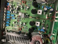
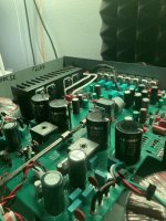
I adopted another modification recommended for Naim amplifiers and added additional power supply capacitors (Nichicon UFW 2200uF 63v) directly to the collector of each output transistor.
ground lands above and below:
Nichicons installed on underside of PCB with double sided tape for additional support/insulation:
As per the original linked article, the result is incredible control and punch together with further improved depth and height of soundstage - I'd definitely recommend considering it.


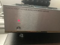
Yes. You can do it!The interior of A3 and A300 looks the same, except for a pair of SAP15. Is it possible to add 1 pair of SAP15 and this MF A3 will become MF A300?
Attachments


- Home
- Amplifiers
- Solid State
- Musical Fidelity A300 coupling capacitors