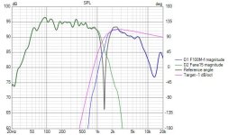
So I should look to decrease the db level of the output of the horn driver to flatten this spike out?
Let's not mix up the two spikes, I'm talking about the crossover, not the one above 2kHz. If you reduce the response at the crossover frequency, you have to do both otherwise the frequency changes.. unless that's what you want.
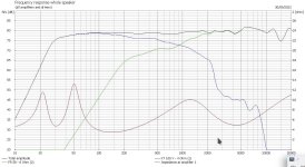
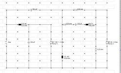
I traced the the curves for the woofer and the compression driver and put together this XO. I used the diffraction tool on the woofer and just the raw data from the compression driver because I have no idea how to model the horn. Here is the XO, obviously there needs to be measurements to get this right, but it looks like a fairly simple crossover might be possible. Is the huge impendence spike at 2kHz is the resonant frequency of the compression driver?
Attachments
Thanks, I was just about to do the same!and put together this XO
impendence spike at 2kHz is the resonant frequency of the compression driver?
seems so.
in addition the "linkwitz riley" low pass with the thread starters values creates a 2 kHz resonant peak.
Also a combination of 20 uF series cap and 75 uH parallel coil makes the impedance drop to near 0 ohms at 1,5 and 5 kHz. Kills the amp.
The impedance drops to 0 = dead short.
Look at the peaks in the electrical transfer function. What you are looking for is a smooth roll off in most cases.
When we talk crossover slopes and orders we refer to the final acoustic slopes not electrical. That is placing 4 components doesn't create a 4th order LR. It's the acoustic / final response of the driver that must follow the 4th order LR to be called that with 360 degrees phase rotation
Ah so I want to make my crossover lines smoother first before looking to change the app response?Let's not mix up the two spikes, I'm talking about the crossover, not the one above 2kHz. If you reduce the response at the crossover frequency, you have to do both otherwise the frequency changes.. unless that's what you want.
Yeah I believe it is. For modelling the horn will I be able to do this with a measurement with the compression driver mounted to the horn in the box?? Thank you very much for that design it looks like it might actually yield a good wood from my cabinets!Is the huge impendence spike at 2kHz is the resonant frequency of the compression driver
I’m getting the driver and other measuring bits and pieces on order so will be able to provide some more meaningful frd files soonsuspect that the horn will change both the frequency response and the impedance of the compression driver. Until you can measure the driver on the horn I would ignore the spike. I have no experience with horns so I will leave it to others to explain what is going on.
Ah so the name of the crossover refers to the electrical response created rather than the components used to create it?When we talk crossover slopes and orders we refer to the final acoustic slopes not electrical. That is placing 4 components doesn't create a 4th order LR. It's the acoustic / final response of the driver that must follow the 4th order LR to be called that with 360 degrees phase rotation
Well sort of.... the name of the crossover = driver in box response + crossover / filter applied. that is - your LR4 at 2KHz would be what the final response looks like for the driver - allowing for all the crossover manpulation. for a woofer already rolling off, a simple 2nd order electrical (coil and cap) may be all that is required to reach the LR4 target.
In otherwords - you may not need a 4th order electrical filter (2 coils and 2 caps) to get a 4th order LR response.
I prefer to call the order of the crossover components the "electrical filter". It alone has it's own order when allowing for driver impedance.
In otherwords - you may not need a 4th order electrical filter (2 coils and 2 caps) to get a 4th order LR response.
I prefer to call the order of the crossover components the "electrical filter". It alone has it's own order when allowing for driver impedance.
The biggest problem for me is the Eminence tweeter. I don't know what horn was used by Eminence when they measured its frequency response. Are you planning to use the same horn? If not, then all bets are off. You really need to measure to know. It may be possible to simulate, but beyond my knowledge.
I see makes more sense to put less components in the way of the drivers then if I’m going to get the same response. The crossover that mtidge posted seems to be a good one to go forIn otherwords - you may not need a 4th order electrical filter (2 coils and 2 caps) to get a 4th order LR response.
I prefer to call the order of the crossover components the "electrical filter". It alone has it's own order when allowing for driver impedance
I haven’t a clue either to be honest. I’ve not got a horn, it was originally used for a soundlab piezo tweeter but I’m just going to chuck the piezos and opt for a higher quilts compression driver in the eminence. I think as you’ve mentioned the best way to do this is to get a measurement of the two together to see what will actually happen when they’re in the box. You said that the impedance might change with the horn is this because the driver will have to work harder within a certain type of horn?The biggest problem for me is the Eminence tweeter. I don't know what horn was used by Eminence when they measured its frequency response. Are you planning to use the same horn? If not, then all bets are off. You really need to measure to know. It may be possible to simulate, but beyond my knowledge.
I was just saying, try keeping phase within 90 degrees of each other.Ah so I want to make my crossover lines smoother first before looking to change the app response?
Interesting video on passive cross overs done by a pro
https://www.youtube.com/live/kUrxAU7f78c?si=kpgw5IzuxbLUF00E
I've already found bits do need adding to a std cross over for other reasons, Now to see if I can implement his ideas.
Mentions one on woofers but can't find it.
https://www.youtube.com/live/kUrxAU7f78c?si=kpgw5IzuxbLUF00E
I've already found bits do need adding to a std cross over for other reasons, Now to see if I can implement his ideas.
Mentions one on woofers but can't find it.
I was bored today with no internet so I made a second attempt at an XO. This one has a smaller impendence spike, a better null with the tweeter reversed. The driver offsets are just WAGs so take this for what it is.
Attachments
Thank you both for the crossover designs I’m getting the drivers and mic ordered this week so should be able to provide better measurements for further designs sometime next week!
An F3 of 30Hz is rather low for a 100mm driver. Max SPL due to xmax is ~78dB. Not enough really so don't take the numbers seriously. Max drive at ~50Hz is ~3vrms.
😉 I bought these drivers - really it's best to do the design firts. They may be ok with an F3 of 40Hz, almost bound to be at 50,
😉 I bought these drivers - really it's best to do the design firts. They may be ok with an F3 of 40Hz, almost bound to be at 50,
- Home
- Loudspeakers
- Multi-Way
- My first passive crossover design!


