It is my personal experience with the 6x4 that it can cope with any amount of capacitance after the choke - thats right it can cope with 100's uf after the choke. i have been running one this way for well over a year. The original published power supply is undoubtedly the minimum needed to get this circuit quite. I would put significant money on the power supply been the source of almost all of your hum issues.
As for the PSU2 you want the output ripple to be in mV and you want the rise time to be over a few seconds without any overshoot and ringing. That looks like a steep but smooth curve leveling out to your final voltage. You need to model it for a resistive load rather than a CCS and for that you need to use ohms law to calculate the resistor which matches your circuit load.
Best to go with the power supply exactly shown in the original schematic.
Shoog
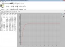
Last edited:
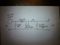
On this side of the world is very hard to get anything, I must winding my own transformers, so I hate them, almost much as chokes.
Many years ago, the Dutch elektor made my life easier.
Since then, I make regulated power supplies for everything, with MOSFET/OPAMP/Voltage reference.
Maybe this could help, only as a guide, with small PSRR of SRPP (my favourite topology)
Many years ago, the Dutch elektor made my life easier.
Since then, I make regulated power supplies for everything, with MOSFET/OPAMP/Voltage reference.
Maybe this could help, only as a guide, with small PSRR of SRPP (my favourite topology)
Attachments
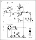
Ok thx. It's very small text. Can't hardly read it. You have it in any better resolution?
Shoog: I'm gonna later use 6X5GT (have the russian eq. of this one) was it 6U5S? Don't remember. Don't have any 7pin to mount in chassie, and i like the octal socket") the 6x4-R is just for "now".
the 6x4-R is just for "now".
Shoog: I'm gonna later use 6X5GT (have the russian eq. of this one) was it 6U5S? Don't remember. Don't have any 7pin to mount in chassie, and i like the octal socket
the 6x4-R is just for "now".Ok thx. It's very small text. Can't hardly read it. You have it in any better resolution?
Sorry, no, but you can download the file and open it at bigger size, so text is clearer.
Ok thx. It's very small text. Can't hardly read it. You have it in any better resolution?
Shoog: I'm gonna later use 6X5GT (have the russian eq. of this one) was it 6U5S? Don't remember. Don't have any 7pin to mount in chassie, and i like the octal socket
Still the point holds - after the choke don't be afraid of using lots of uF. This is where PSU2 comes in as it will tell you if you are stressing the rectifier valve.
Shoog
Hi,
If there was no cap then, yes. if these replaced an existing electrolytic cap then I'd expect higher ripple levels iso lower ones.
Ciao,
I remember that when i put that 4,4uF MKP before choke hum almost dissapeard.
If there was no cap then, yes. if these replaced an existing electrolytic cap then I'd expect higher ripple levels iso lower ones.
Ciao,
It could still be marginal - but it looks better.
Unfortunately we need more information to answer the question accurately, in the form of exact current and voltage draw. Without it you would need to build it and listen or preferably measure its output with an oscilliscope.
Shoog
Unfortunately we need more information to answer the question accurately, in the form of exact current and voltage draw. Without it you would need to build it and listen or preferably measure its output with an oscilliscope.
Shoog
It could still be marginal - but it looks better.
Unfortunately we need more information to answer the question accurately, in the form of exact current and voltage draw. Without it you would need to build it and listen or preferably measure its output with an oscilliscope.
Shoog
Voltagedrop over droppres 13,35v -12mA (each tube around 5mA)
B+ next to tubes= 250v
Transformer sec: 230-0-230 - 0,04mA
I don't know any more i think.
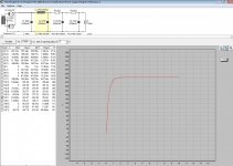
If it were me I would go with a C-L-C-R-C-R-C arrangement with the MKP right off the xformer and before the choke. The rest would be good electrolytics.
Sims pretty good too I think.
llooks good. Prefer theslower rise time and easier load of the second. Last cap should be film cap of around 10uf.
Shoog
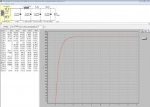
Here is a 10uF - 47uF - 120uF - 10uF - rises even slower with a larger cap in position 3.
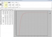
and now 40uF - 47uF - 120uF - 40uF - the 47uF in the third position works OK but 120 has a nicer curve. Either one would work though
and now 40uF - 47uF - 120uF - 40uF - the 47uF in the third position works OK but 120 has a nicer curve. Either one would work though
Attachments
Last edited:
- Status
- This old topic is closed. If you want to reopen this topic, contact a moderator using the "Report Post" button.
- Home
- Amplifiers
- Tubes / Valves
- My first preamp with tubes