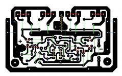
Stop!. Beware... this version of PCB has an error that was never corrected. Its regarding R10 connected to gnd. it should be to -ve rail as pointed by some gentleman...
Hi
You was right about that resistor, I fix it but I would love to go over on all the layout for double check.
Sorry guys I misunderstood the whole I thought that PC board was already tested and built..
Did you found other mistakes to?
Greetings
Attachments
Hi
You was right about that resistor, I fix it but I would love to go over on all the layout for double check.
Sorry guys I misunderstood the whole I thought that PC board was already tested and built..
Did you found other mistakes to?
Greetings
Hi,
I havent been thro all the layout thoroughly. if u give me 2-3 days time, I am putting it in eagle software that has ability to check schematic and layout.
Alexmm layout that is referenced in first post has been tested by still4given. post #300 or so.
Hi,
I havent been thro all the layout thoroughly. if u give me 2-3 days time, I am putting it in eagle software that has ability to check schematic and layout.
Alexmm layout that is referenced in first post has been tested by still4given. post #300 or so.
I know about that, that layout does not feet my heatsink that is why I choose these.
Even these was heavily modified but I kept all the components how Alex designed.
Only I corrected the R10.
I will check these thoroughly before I fabricate the PC boards.
Greetings
Every component line up nice how Alex deigned R10 corrected.
If someone could go over on ALEX layout that would be helpful. More people check the layout we have better chance to find errors if there is any left..
Thank you
Again I do like these layout and easy to make it with iron transfer...
Greetings
If someone could go over on ALEX layout that would be helpful. More people check the layout we have better chance to find errors if there is any left..
Thank you
Again I do like these layout and easy to make it with iron transfer...
Greetings
Attachments
Last edited:
Karl,
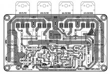
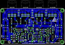
Here is your amp layout based on alexmm layout, i made. There was some mistakes on the alex mm layout (R10, repeat notations, popular cap sizes, etc.). I have corrected. but he is master in layout!!.
a) Feed back point as per your suggestion.
b) inductor on speaker terminal.
c) extra holes for emitter resistor pitch (15.75mm, is enough?).
d)MT trimmer for R8, can be replaced after finding correct value.
please tell if it need improvement.
octave1.
Attachments
That looks good
I'll have a closer study of it later, possibly tomorrow. The feedback point looks OK, as to the resistor size, you would have to see what parts are available in your locale and design to suit but if you have used standard sizes then it should be fine.
The trimmer... I've long held the view that passing current through the wiper of a preset isn't good from a reliability point of view but modern devices such as from Vishay actually quote wiper current, and for example the 500 ohm 64Y series its 32ma, way above the 6 ma seen here. So maybe the advise to replace with a fixed value isn't so clear cut nowadays, at least if you can verify the quality of the part being fitted.
I'll have a closer look later.
Karl,
Here is your amp layout based on alexmm layout, i made. There was some mistakes on the alex mm layout (R10, repeat notations, popular cap sizes, etc.). I have corrected. but he is master in layout!!.
a) Feed back point as per your suggestion.
b) inductor on speaker terminal.
c) extra holes for emitter resistor pitch (15.75mm, is enough?).
d)MT trimmer for R8, can be replaced after finding correct value.
please tell if it need improvement.
octave1.
It does look nice! I went over and I see no error ... It looks good to go but some other guys should go over to.
Only one question why you connected the feedback resistor that way, I want to learn if any secret or any advantage.
All do I will stick with my own layout (I build only one amp and I spent way to much on PC boards I could produce it at home last year. They are still in my box.
Having said that professionally made PC boards give more value to the amplifier at least I feel that way. These amplifier (design) would deserve a GB even do I will not participate.. I will use my own made PC board.
Thank to Mooly - Alex and Octave
The feedback take off point is the only point in the output stage where the output signal is at its purest. The reason is because of the finite resistance of all the PCB print and wiring and component leads which means that if you measure the amplifier output at any other point then you will see a rise in distortion. The feedback take-off point is the single point that the feedback network can correct and ensure the output is a faithful copy of the input.
If we moved the feedback take-off point to the end of R23 for example, then that point would become the 'perfect' output point of the amplifier and we would take the speaker from there.
Its all because the print has resistance, and so it develops a voltage across it when delivering current. Taking the speaker feed from the feedback point eliminates that problem. If you get it wrong then you worsen the distortion by anything from 5 to 10 to perhaps a 100 fold.
It does look nice! I went over and I see no error ... It looks good to go but some other guys should go over to.
Only one question why you connected the feedback resistor that way, I want to learn if any secret or any advantage.
All do I will stick with my own layout (I build only one amp and I spent way to much on PC boards I could produce it at home last year. They are still in my box.
Having said that professionally made PC boards give more value to the amplifier at least I feel that way. These amplifier (design) would deserve a GB even do I will not participate.. I will use my own made PC board.
Thank to Mooly - Alex and Octave
Thank you!. The reason why I dont trust untested layout made in sprint that dont have checking ability with schematic, because there is chance for error. but with cad like eagle, diptrace there is no chance for wrong connection if you carefully select devices when making the schematic (e.g. ECB or BCE, etc). schematic correct= layout correct (with some know-how like where to take feedback point, etc).
I dont have skill to make PCB at home
, but my city there is simple PCB fabricator (only single sided ) that gives me 3-5$ per PCB. I am happy with quality. all the best for your building of this amplifier. I sure you will be happy to listen.Thank you Mr. Karl. I will see whats available here and also at farnell and keep the spacing as per those. can you show me an example of vishay non-inductive resistor ?That looks good
I'll have a closer study of it later, possibly tomorrow. The feedback point looks OK, as to the resistor size, you would have to see what parts are available in your locale and design to suit but if you have used standard sizes then it should be fine.
The trimmer... I've long held the view that passing current through the wiper of a preset isn't good from a reliability point of view but modern devices such as from Vishay actually quote wiper current, and for example the 500 ohm 64Y series its 32ma, way above the 6 ma seen here. So maybe the advise to replace with a fixed value isn't so clear cut nowadays, at least if you can verify the quality of the part being fitted.
I'll have a closer look later.
regards
octave1
Thank you Mr. Karl. I will see whats available here and also at farnell and keep the spacing as per those. can you show me an example of vishay non-inductive resistor ?
regards
octave1
Don't bother, got it here. http://www.vishay.com/docs/31801/mra.pdf. 16.51mm. I will make modifications to keep it 18.5mm lead pitch spacings.
32mA for a 500mW 500r potentiometer is right up at the maximum rating for the device.That looks good
I'll have a closer study of it later, possibly tomorrow. The feedback point looks OK, as to the resistor size, you would have to see what parts are available in your locale and design to suit but if you have used standard sizes then it should be fine.
The trimmer... I've long held the view that passing current through the wiper of a preset isn't good from a reliability point of view but modern devices such as from Vishay actually quote wiper current, and for example the 500 ohm 64Y series its 32ma, way above the 6 ma seen here. So maybe the advise to replace with a fixed value isn't so clear cut nowadays, at least if you can verify the quality of the part being fitted.
I'll have a closer look later.
0.032A²*500r = 512mW
If you were using a fixed resistor you would usually run it at a maximum dissipation below 50% of the maximum rating and for sensitive locations maybe even below 10% of the maximum rating.
I would NEVER run the wiper of a VR at 100% of maximum rating. I suggest half power as an absolute maximum (half power is 0.7071*32mA = 22mA), or what I adopt is half maximum current which equals 25% of maximum power, i.e. <16mA for a 500r 500mW pot.
6mA is 3.6% of maximum power rating. This is OK for reliability.
And is significantly less than 10% of maximum power rating.
Last edited:

It's not the wattage over the actual value of the resistances that matters.In this amplifier the bias setting resistor only sees around 1.4 volts across it and will be set somewhere in the 180 to 260 ohm region give or take. The wattage dissipated in the trimmer is not going to be much over 10 milliwatts worse case.
View attachment 526680
It's the proportion of the absolute maximum current that matters. This is what passes along the track and through the wiper. If the wiper was always at maximum resistance then max power and max current become the same limitation.
But when the resistance is turned lower, then it is CURRENT that becomes the limit.
6mA or 7mA through a 500mW 500r pot is not a problem.
The maximum equivalent power would be 0.006A²*500r = 0.018W, or 3.6% of maximum rating.
Last edited:
Yes... isn't that what I'm saying.
The trimmer will be set to say 220 ohm. The wiper will always see 6ma flowing as that is a constant (and that value is well within the 32ma limit) and so the dissipation over the part of the resistive track that's in use will be 7.9 milliwatts.
The trimmer will be set to say 220 ohm. The wiper will always see 6ma flowing as that is a constant (and that value is well within the 32ma limit) and so the dissipation over the part of the resistive track that's in use will be 7.9 milliwatts.
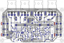
I've looked the board over and it seems fine (values of the 22pf and 150pf are swapped though).
Mr. Karl,
Good Catch!!. Yes, only the value on silk was swapped on layout, electrically ok. Corrected. I am also putting some options for pitch spacing for caps, etc . so that people can use whatever is available to them.

- Home
- Amplifiers
- Solid State
- My MOSFET amplifier designed for music