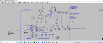
Mine isn't fixed either.I keep forgetting you have the advantage of a fixed load so optimisation is a reality
OK, understood.
I use 6922 tubes in an SRPP output stage in my audio mixer designs. I have a variable load depending on what routing is selected and if the direct outputs are used or not and so on. Basically the load can vary from from moderate to heavy. My version outputs +26dBu into a 600 ohm load with a 300V supply (that is 400mW) using a 2:1 output transformer. There would typically be 20 or more such stages in a mixer quiescent current has a big impact on the power supply so it is set to be sufficient to drive the worst case load rather than to optimise the SRPP. Dissipation is also an issue with so many tubes in a smallish enclosure.
Of course Merlin would say this is exactly the application where you would NOT use an SRPP.
Cheers
Ian
My Sowter's have 3 secondary coils used for 3 difference ranges of headphone Z.
So my Zload can vary between 3600-14400.
After much thought, I chose to optimise for 4940Ω as this corresponds closer to headphone values I'm be more likely to hookup with most others coming in at a higher Z to the one optimized for.
Some compromising, no doubt, but consider this:
The SSRP is currently set-up for a Zload of 300Ω ('cause I'm an idiot) and my Sennheisers are 50Ω, reflected as 7200Ω and it still has plenty of power despite the gross mismatch.
I can't wait for the parts to arrive to put this right.
Here's an OTL version, designed for 50 ohm headphones.
I also simplified the PSU - requiring only 1 choke.

I also simplified the PSU - requiring only 1 choke.
I am a sucker for nice finish, would you mind sharing how you painted your enclosure? Everytime I try to spray hammered paint, it ends up leaking on the faces. What kind of primer did you use? Is it an aluminium chassis or steel? Thanks!
The reason it has plenty of power is because the quiescent current is so high. I very often hear people saying this preamp or whatever has a very low output impedance (especially if it is a white follower) but all to often they forget that these figures are derived from theory and are actually small signal values. These tell you nothing about the drive capability of the stage which is determined principally by the quiescent current. Basic theory only takes you so far. Thereafter you need the thing on the bench to make measurements of reality.Mine isn't fixed either.
My Sowter's have 3 secondary coils used for 3 difference ranges of headphone Z.
So my Zload can vary between 3600-14400.
After much thought, I chose to optimise for 4940Ω as this corresponds closer to headphone values I'm be more likely to hookup with most others coming in at a higher Z to the one optimized for.
Some compromising, no doubt, but consider this:
The SSRP is currently set-up for a Zload of 300Ω ('cause I'm an idiot) and my Sennheisers are 50Ω, reflected as 7200Ω and it still has plenty of power despite the gross mismatch.
I can't wait for the parts to arrive to put this right.
Cheers
ian
Hi.I am a sucker for nice finish, would you mind sharing how you painted your enclosure? Everytime I try to spray hammered paint, it ends up leaking on the faces. What kind of primer did you use? Is it an aluminium chassis or steel? Thanks!
It's an aluminium Hammond chassis.
After cutting out the holes, I washed it with dish washing soap and warm water.
Then I used a fine grit sandpaper on the outside surface for the paint to key into.
Rinsed out the dust.
Then I sprayed etch primer in 2 or 3 light coats, allowing 15 min between them.
Then I sprayed with paint in 3 or 4 coats, always careful to keep the coats light so as not to run.
After 20 minutes it's touch dry but it'll need a few days for the paint to harden.
If you're careful, you can proceed with assembly after 24hours.
Good luck
Last edited:
Thanks!Hi.
It's an aluminium Hammond chassis.
After cutting out the holes, I washed it with dish washing soap and warm water.
Then I used a fine grit sandpaper on the outside surface for the paint to key into.
Rinsed out the dust.
Then I sprayed etch primer in 2 or 3 light coats, allowing 15 min between them.
Then I sprayed with paint in 3 or 4 coats, always careful to keep the coats light so as not to run.
After 20 minutes it's touch dry but it'll need a few days for the paint to harden.
If you're careful, you can proceed with assembly after 24hours.
Good luck
When sanding, make sure you remove all the shininess - make it look like brushed stainless steel.Thanks!
And when spraying, move your entire arm side to side so the distance between the nozzle and chassis is constant - don't just turn your wrists 👍
Just finished tweaking the amp. I corrected my mistake of assuming that the sowter transformers input impedance was a constant 300Ω... It's not. Z varies with the headphones plugged in and the range I selected. So the SRPP output stage wasn't optimized, for example, my 50Ω phones reflected 7200Ω, etc.
The SRPP was working as a single ended stage only.
Now it's properly stretching it's legs as a push pull.
It was loud before - now it hurts my ears with the volume at 4 o'clock with clean sound.

The SRPP was working as a single ended stage only.
Now it's properly stretching it's legs as a push pull.
It was loud before - now it hurts my ears with the volume at 4 o'clock with clean sound.
The good old SRPP output stage is certainly able to deliver real power when set up correctly. Enjoy.
Cheers
Ian
Cheers
Ian
Thanks for your help!The good old SRPP output stage is certainly able to deliver real power when set up correctly. Enjoy.
Cheers
Ian
I fashioned together a 33 ohm dummy resistor and with my oscilloscope i verified output voltage to be 4v p2p.
With a 2v input signal i can max out the volume pot with clipping only just beginning to show up on the scope if i turn the pot fast but the NFB deals with it - easily seen on screen, producing a clean sine wave.
At 3v input, I have to turn the pot back to about 4 o'clock to prevent clipping.
This all works out to 60 mWrms.
HF roll-offs only slightly - roughly 3.8v p2p on the scope at 20khz.
However, at 20hz I was getting 2v p2p which I wasn't happy about - soundwise I didn't notice a lack of bass but the scope doesn't lie so I ended up swapping out the 4.7uf parafeed capacitor for a 22uf poly and then I tweaked the parafeed LF resonant "hump" by swapping out the huge 100uf cap in the NFB loop for a 47uf poly.
I now have a flat LF response down to 20hz @ 4v p2p, only rolling off below that with 0v at 1hz and the LF hump pushed back further down into the mhz.
It sounds amazing.View attachment 1020714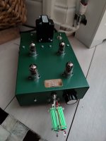
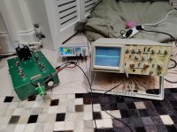
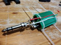 View attachment 1020714
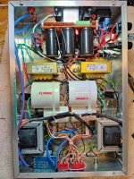
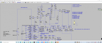
With a 2v input signal i can max out the volume pot with clipping only just beginning to show up on the scope if i turn the pot fast but the NFB deals with it - easily seen on screen, producing a clean sine wave.
At 3v input, I have to turn the pot back to about 4 o'clock to prevent clipping.
This all works out to 60 mWrms.
HF roll-offs only slightly - roughly 3.8v p2p on the scope at 20khz.
However, at 20hz I was getting 2v p2p which I wasn't happy about - soundwise I didn't notice a lack of bass but the scope doesn't lie so I ended up swapping out the 4.7uf parafeed capacitor for a 22uf poly and then I tweaked the parafeed LF resonant "hump" by swapping out the huge 100uf cap in the NFB loop for a 47uf poly.
I now have a flat LF response down to 20hz @ 4v p2p, only rolling off below that with 0v at 1hz and the LF hump pushed back further down into the mhz.
It sounds amazing.View attachment 1020714


 View attachment 1020714

Last edited:
Yes.Looks like you cracked it. The HF roll of is probably due to C16.
Cheers
Ian
It's only slight and i planned it liked that as a means of avoiding oscillation beyond the audio range.
60mWrms sound reasonable to you?
60mW should be enough for most 32 ohm phones. It depends on their sensitivity. 60mW is nearly +18dBm. My usual rule of thumb is that 117 db SPL is dangerous to hearing. So with +18dBm of power, any phones with a sensitivity of 99 dB SPL per mW or less will be safe.Yes.
It's only slight and i planned it liked that as a means of avoiding oscillation beyond the audio range.
60mWrms sound reasonable to you?
From the design point of view, I use a 6922 SRPP output stage running at about 6mA for my line level outputs. With a 250V HT and through a 2:1 transformer this will output over +20dBu into 600 ohms which is 100mW so you are definitely in the right ball park.
Cheers
Ian
- Home
- Amplifiers
- Tubes / Valves
- My Newly Scratch-Built Tube Headphone Amplifer
