I have an old NAD C521i CD player that I use occasionally & the display is VERY dim, in fact I thought it was dead but eventually noticed there was still some life left in it.
I have downloaded the manual but really for me it's like trying to read a foreign language.
It's not worth sending to the shop to get fixed, but I was hoping to keep it going if I can.
Does anyone have any idea what the problem might be?
I did find a thread from 2006 that I thought was going to get me there but it turned out the capacitors that the fellow replaced to fix his problem dont seem to exist in my player.
Attachments

Last edited:
I have an old NAD C521i CD player that I use occasionally & the display is VERY dim, in fact I thought it was dead but eventually noticed there was still some life left in it.
I have downloaded the manual but really for me it's like trying to read a foreign language.
It's not worth sending to the shop to get fixed, but I was hoping to keep it going if I can.
Does anyone have any idea what the problem might be?
I did find a thread from 2006 that I thought was going to get me there but it turned out the capacitors that the fellow replaced to fix his problem dont seem to exist in my player.
I think there should be a voltage of 3.3 - 4 V and another oven higher abt 40V, meassure the secundar winding on your trafo.
The big question is whether this is an LCD or a VFD display.
The LCD is backlit via small filament bulbs... a common problem.
The VFD (vacuum flourescent display) can suffer with low emmision, usually some segments are brighter than others and can "recover" after many hours use.
This type of display often suffers from "capacitor trouble" in the supplies derived to feed it... very common across all types of equipment that use this type of display.
If you post the circuit we can advise...

R709 in that diagram appears to be a preset pot... I assume to set the brightness of the display ?
R709 in that diagram appears to be a preset pot... I assume to set the brightness of the display ?
WOW your fast, thanks, it will be a couple of days before I get the chance to pull it apart.
What do you mean "check by substitution".
I have no idea what R709 does but I will have a play when I get it apart.
THANKS
David
Without using a scope to see if there is any high frequency noise or ripple on the supply the only sure way to test the caps is to remove and replace with new (check by substitution).
R709 varies the supply available to the transistor Q520. I haven't read the manual... there may be a procedure for adjusting it but I would still change the caps first before doing anything.
Q520 forms a simple oscillator (with transformer M501) to generate a high voltage for the display.
Good luck... any questions just ask.
I'm not saying the display isn't faulty... it may be... but caps are such a common problem that it makes sense to check them first.
Without using a scope to see if there is any high frequency noise or ripple on the supply the only sure way to test the caps is to remove and replace with new (check by substitution).
R709 varies the supply available to the transistor Q520. I haven't read the manual... there may be a procedure for adjusting it but I would still change the caps first before doing anything.
Q520 forms a simple oscillator (with transformer M501) to generate a high voltage for the display.
Good luck... any questions just ask.
I'm not saying the display isn't faulty... it may be... but caps are such a common problem that it makes sense to check them first.
How important is it to match the capacitor values exactly?
No matching required at all... just stick to the original values and choose at least as high a voltage rating as the originals.

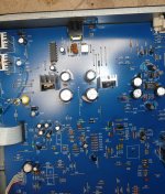
No joy I'm afraid, I replaced the caps & there is no change. There is a ringing noise coming for the PCB somewhere in the vicinity of the larger caps on the baord as per the photo, any idea what that might be about? It's a bit hard to pin down the exact location
Attachments
I had one of those players back in the day... It had a dim display because the incandescent backlight bulb had burnt out. Are you sure that isn't the case with yours? Or does it have the EL backlight?
~Tom
~Tom
What is the DC voltage across C522 ? Make a note of it.
Now alter that preset pot a little and see if the display alters. If not then reset voltage back to where it was.
Now alter that preset pot a little and see if the display alters. If not then reset voltage back to where it was.
I not sure how successful this would be but I think it is worth trying to measure on your meter the voltage at point "ELD1" on the circuit in post #4. Make sure your meter is on AC volts and a highish range, say 200vac.
Also check the 9 volts is correct at the output of the 7809 regulator. Perhaps do that first. It should be spot on.
Hard to say what the ringing is... in general terms it can be typical of failed capacitor in any switching supply... and the EL driver is just that.
Also check the 9 volts is correct at the output of the 7809 regulator. Perhaps do that first. It should be spot on.
Hard to say what the ringing is... in general terms it can be typical of failed capacitor in any switching supply... and the EL driver is just that.
I not sure how successful this would be but I think it is worth trying to measure on your meter the voltage at point "ELD1" on the circuit in post #4. Make sure your meter is on AC volts and a highish range, say 200vac.
Also check the 9 volts is correct at the output of the 7809 regulator. Perhaps do that first. It should be spot on.
Hard to say what the ringing is... in general terms it can be typical of failed capacitor in any switching supply... and the EL driver is just that.
I was way wrong about the ringing noise position, it stops when I pull out the small power plug for the display, so its the display that's making the noise.
Attachments

The regulator seems to be at approx 11V, turning the pot made no difference, I will have to pull the PCB out again to check the voltages on the capacitor & ELD1. I cannot do that until tomorrow 🙂
OK... if the output of the reg is at 11 v dc then there is a problem.
Can you make 100% sure on that reading. It should be 9 volts DC between ground and pin 3 of the regulator.
If its high then that is a sign of ripple on the rail and that could be cap C518 just before the reg.
Edit... did you swap that cap ?
Can you make 100% sure on that reading. It should be 9 volts DC between ground and pin 3 of the regulator.
If its high then that is a sign of ripple on the rail and that could be cap C518 just before the reg.
Edit... did you swap that cap ?
With the plug back in what is the voltage on the two leads into the plug. Just stick your meter probes in carefully.
Measure on both AC volts and DC volts and see what reading you get.
Measure on both AC volts and DC volts and see what reading you get.
Looking at the PCB layout the two solder blobs next to the plug are the same points so you can measure across those if its easier.
OK... if the output of the reg is at 11 v dc then there is a problem.
Can you make 100% sure on that reading. It should be 9 volts DC between ground and pin 3 of the regulator.
If its high then that is a sign of ripple on the rail and that could be cap C518 just before the reg.
Edit... did you swap that cap ?
I did replace C518
There is 11V on the leg closest to the front of the CD player, and 8.85V on the other leg
Attachments

- Status
- Not open for further replies.
- Home
- Source & Line
- Digital Source
- NAD Display Very Dim