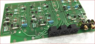
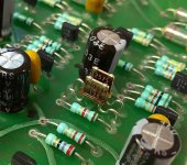
No, not according to this pic, which the review author alleges is the same board before new components were fitted. Well, not exactly before, because the original 2 resistors appear to be close tolerance types similar in form to MF resistors and probably the same types as those shown in your pic.Yes those "dark brown, upright gizmos" are resistors. Did you say Naim fitted these?
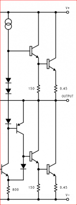
My guess is that Naim set the channel balance with precision resistors, not a trimpot and these are said to be in the feedback loop but not shown on the sketch of the schematic I posted. I wonder if there were various balance setting methods used during the time Nait2 was produced? There were other products like the Supernait which followed but I'm just considering the Nait2 which was somewhat special and still a popular model to look for.
Edit: I should have been clear that the replacement of the semis would likely mean a new balance setting was necessary, hence the need for replacement resistors.
Attachments
Last edited:
Member
Joined 2009
Paid Member
Do you mean that precision resistors were needed in the feedback loop, which is where the gain is controlled ? - because back then resistors had poor tolerance. Is it possible it was for dc-offset instead ? - I only see one pot per channel and that was very likely for the idle current.
I'm not convinced this has anything to do with Naim at all.
FYI some company doing "upgrades" using those resistors: Naim Audio Service and Restorations
FYI some company doing "upgrades" using those resistors: Naim Audio Service and Restorations
Attachments
Member
Joined 2009
Paid Member
Yes, the pots are the usual bias adjusters but the 2 odd resistors were apparently only needed in one channel which would be all that was necessary to balance the gain by selecting the values after testing the board assemblies. According to comment on this feature at PFM, this was indeed the purpose and it would need re-doing after any serious repairs too.Do you mean that precision resistors were needed in the feedback loop, which is where the gain is controlled ? ....... I only see one pot per channel and that was very likely for the idle current.
Last edited:
Ah...not quite true. I'll correct myself and say it was Nait1 that was designed for balance adjustment by varying gain in only one channel but Nait2 had factory settings applied to both. Maybe there were issues with servicing or more likely, it was about complaints of the limited range of adjustment and meeting the power output spec. i.e. the old question about whether Nait2 was consistently good for 18WRMS or just 15WRMS per channel.
It seems those flat resistors are a film type which is allegedly better for sound quality than MF. Why you'd only fit them there is puzzling but who knows what is in the mind and methods of audiophile upgraders?
It seems those flat resistors are a film type which is allegedly better for sound quality than MF. Why you'd only fit them there is puzzling but who knows what is in the mind and methods of audiophile upgraders?
Why you'd only fit them there is puzzling but who knows what is in the mind and methods of audiophile upgraders?
Attachments

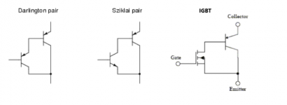
Answers submitted include difficulties/performance issues with opposite polarity BJTs on the same die, stability, less good for switching. Better for audio amps to have the dies physically separated for better temp compensation.Quiz:
1) You can easily buy a Darlington transistor. Why don't you see pseudo-Darlington/CFP/Sziklai transitors for sale?
Any guesses?2) What modern device can you buy that has some similarity to a pseudo-Darlington?
Member
Joined 2009
Paid Member

..... Any guesses?
 Chipamps with quasi-complementary output stages? Perhaps a voltage regulator of some type? The LM3886 is credited with being a quasi-complementary design with a PNP driver, albeit a pre-driver in the negative rail side of a triple.
Attachments
OK, an SCR or thyristor. There's a nice tutorial on them at the link for anyone who doesn't have much experience or knowledge of them, since they are usually seen in early solid state power or motor speed control circuits. I don't recall seeing any serious use for them in linear amplifiers other than as crowbar safety devices. https://www.electronics-tutorials.ws/power/thyristor.html
Last edited:
Ah yes, shades of the eponymous "Alexander Amplifier". https://www.analog.com/media/en/tec...tes/58052492001115525484056221917334AN211.pdf
Have fun with that one
Have fun with that one
I am not normal. I do not accept the worthiness of something solely based on the authority of the publisher.
For example, I look at that Analog Devices note and wonder how it ever got approved by someone at AD to carry the esteemed AD brand name. I also have to feel sorry for the University of Toronto. Then I remember they are just trying to sell AD op-amps.
Anyhow, I would not tar and feather the IGBT device based on this application note. The IGBT has some very interesting characteristics that can be exploited in linear audio. I am also tickled when I read some IGBT datasheets that include welding in the list of typical applications! A true super-transistor.
Last edited:
The point of the design, as I remember from many years back, seemed to be the novelty. Think of the brownie points in the EE small hall of fame when you succeeded in using new types of industrial switching devices as the output devices for a hi-fi amplifier. It caused a stir of interest, at least in the output devices and spawned a number of simplified DIY designs, even here in Oz.
Regarding the facts and figures, Eva's posts in this old thread make interesting reading:
IGBT amplifiers
Regarding the facts and figures, Eva's posts in this old thread make interesting reading:
IGBT amplifiers
- Home
- Amplifiers
- Solid State
- NAP-140 Clone Amp Kit on eBay