I'm not quite sure why, possibly an addiction, but I am currently building a pair of P101s:
Project 101 - High Power, High Fidelity Lateral MOSFET power amplifier
VAS current seems to ~5mA for 2 pairs of lateral fets in this design.
I've also got a stereo one of these on the go:
MJR7-Mk5 Mosfet Power Amplifier
Looks like ~20mA in the driver stage for 1 pair of FETs.
Sorry for another OT post!
The beauty of the ESP design is it shares some similarity with the Naim NAP. I would change the VAS in his design. Also his N FET gS capacitor is not helpful. Rod has fallen into the trap of all in that he fails to see CgS is bootsrapped to the load. A sine wave at the source is inphase with the gate. As a result the capacitance no longer has the effect it would have if a grounded source voltage amp where the useful output is in the drain load. Rod also in my opinion has made a small mistake using sources resistors for the larger version. Not really required as FET's do current averaging. Exicon can supply VgS matched sets to make this work very well. If buying 25 this seems to be automatically done. The reason to use multiple FET's is to approximate a bipolar amps bass drive. In theory at least 4 devices ( 4 pairs ) required to mimic one set of Bipolars. In practice that is not really true. I suspect the design of speakers is really the problem.
Rod also shows a very simple current mirror to replace 1K 22K of TR1+2 if the NAP. I strongely approve of Rods very simple version, it would fit without much trouble and be if you like in the Avondale direction of sound. However it will change the slew rate and might need care. What the current mirror does it make every last drop of current available to drive the VAS whilst giving very good balance. What Rod does is say that's good enough and no need to perfect it. In doing this he maintains the mirror's Vce as low as possible at some compromise to ballance. This will give more second harmonic distortion than perfect balance. In theory perfect balance is using this mirror times two. The diode side swapped over on mirror two. Then some emitter resistors to force balance. 68R being typical. If unlucky we are looking that this mirror is at 0.3V above the rail. The VAS base at 0.5V. Even though thought to be a pure current drive of mirror to VAS base it isn't a nice idea. What Rod does is better, 0.1 V is what I suspect he gets. BCV62 and 61 are better than anything you might make yourself with 100 devices to pick from. The VAS base will protect them so making the 20V rating OK. They are big for a surface mount device so easy to use. If making the perfect mirror the big pin swaps sides on mirror 2.
If you looked my VAS idea of a bootstrapped emitter load I should have said you must use a scope to test it. If the capacitor is large it is as if it isn't there. That is, except it allows the VAS base to rise up to whatever DC point required with no loss of loop gain. This could be a powerful tool to use with a current mirror of the " perfect " 4 transistor type.The temptation is to make the capacitor small so as to offer more loop gain at 10 kHz but not lower down. It should occure to us that there will be a phase shift and it could be critical. I doubt it will if the loop gain isn't larger than the standard amp. There is one very exciting possibility in this. The largest power output should be 50 Hz to 3 kHz. If we start to use the bootstrap at 1 kHz we might just do some good. That is where VAS Re = Zbootsrap approximately. This makes the VAS easier to drive upto the point where output drops when the tweeter (and not required). Who knows if better or worse? I suspect an easy to drive VAS sounds bettter and the Panasonic FC cap won't change it much. Smoke from tweeters means Nyquist stablity point exceeded.
Someone was saying how some transistors are fast. That is only ture if you force them to switch off at the class B switch over point. Mostly it's only the 20 kHz needs of audio that hide the fact we seldom manage that. The average power FET modestly claims about 10 MHz switch on. The switch off can be single nanoseconds or much less ( pico seconds ). This is perfect for class B use. For class D it is the only way possible. Pulse lasars need pico second pulses. The on time of all devices is too slow. The only way to do this is to switch off a FET and pull the lasar down rather than up. Simple industrial FET's like audio FET's can be switched off this fast.
Here is a crazy idea that seems was made to work. I love using a power transistor to drive the power transistors. He uses a variation of the Hitach VAS. The Bryston circuits are worth looking at. Crimson is the missing link between Naim and Bryston. It shows how little complexity is needed to get high power.
http://www.diyaudio.com/forums/solid-state/235892-1000w-simple-pa-amplifier.html
http://www.diyaudio.com/forums/solid-state/235892-1000w-simple-pa-amplifier.html
I wouldn't be too concerned. This thread has been trashed to the point now, where you have to scan through many pages of O/T to find anything useful about completing the clone kits, let alone from anyone like Atupi, who has recently built one.
Every design deserves a separate discussion thread and both P101 and MJR7 are interesting but an MJR7 build would be especially interesting. I would have begun one myself some time back, but for lack of a PCB. Why not start a thread about it and post your progress as you go? 🙂
Not really as people return to the how and the why constantly. How does a garage mechanic learn? He or she sees similarities. Lets be honest, these Naim clone kits are not really a good idea for a Newbe. However with some sensible modification they offer the possibility of a taste of the Naim sound circa 1978. As the output transistors have changed since 1978 we have the right to ask how better we can use these kits.
If you look at the Apex design I gave a link to it looks hopelessly wrong ( +/- 110V rails and 1000 watts ). People seems very willing to tell him that. He takes any useful advice and the amplifer becomes reality. It should be possible with the right transistors ( and 63 V caps ) to make the Naim or Avondale clone higher power. MJE 340/350 MPSA 92/42 make it possible, there are better choices. If as a first attempt we say 2 mA TR1+2 and +/- 58 V ( max ) supply that looks fine for TR1/2/3. If VAS is 9mA that is still OK if T0126 devices. TR7/8/9/10 should be 250V types. 120 watts RMS might be possible ( on paper more ). If I did this and the Avondale I would make the 220R on each rail 2K ( to TR4 & 6 ). This would make the amplifier exactly as now for normal use depending on how people power their Avondales. It could be restored to 220R for party mode. The advantage of this is a much cleaner sounding when normal running. I highly approve of the 220R in the design of Les. What it ensures is a much nicer clipping. Les also adds 1K to TR6 base. This prevents latch up of the VAS at clipping. Now that is hyper important. Personally I would use a cooling fan for party mode. The heatsink required for a 200 watt 4R amp if using the large Motorola transistors would cost a fortune and would not be gauranteed to work. The sad part of this story is if you prefer the Big Naim clone it will be because the transformer is larger and the power rails cleaner. You can have all of that without changing the power output. The real life difference between 50 and 120 watts is not vast if the PSU is the same. What we think is power is in fact PSU size. The larger difference we hear is between 8 watts and 100 watts. Even so we mosly are listening to PSU size. Now if Julian is reading this in the real Naim Audio in the sky I suspect he will say " At last the Naim Clone thread is talking real Naim Audio ".
One thing I totally reject is the concept of super amps. Why ? Simply because all of the refinements of the linearity of the circuit become total nonesence when it is used in class AB. The only thing that matters in class AB is loop gain and stability, high slew rates and freadom of latch up are not to be thought stupid. As Rod Elliot of ESP Audio shows even a very simple amp can have a loop gain of 1.8 million. That amp has a chance of working. The proof perfect of this is class D. Any complexity is a disaster, fire is the usual result. The Hypex design is very simple and yet is works. It puts to shame most class AB super amps. The Hypex looks a little like a very simple class AB amp in structure except configured sightly differently. I had a Hypex UCD180 running all day on the inner slide out piece of a Naim Nait at 90 watts. This was like a piece of A4 paper in 2.5 mm metal. It was a mistake as I forgotten I was using the 10:1 probe and had done a full power test. The Hypex was very happy and was smoking the test resistors. BTW, The Bosch 1800 watt half moon oven element is very cheap as a generic. It has a centre fold with metal bar connecting two sections. It will give about 8 ohms as a test resistor centre to ends , it is about 32 R when 230 V use.
Now I find good preamplifier for matching with my ncc200..How about preamplifier naim nap821 or 321?Anybody have pcb ?
You will finder a wider variety of Naim projects and DIY interest here: pink fish mediaNow I find good preamplifier for matching with my ncc200..How about preamplifier naim nap821 or 321?Anybody have pcb ?
Avondale audio sell 821 boards and they are very nice just add a 24v power supply, switch and vol pot
Amplifier Modules | AVONDALE AUDIO
Here is a one I built and it sounds very nice
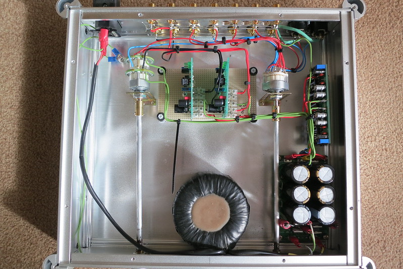 IMG_2375 by Alan Towell, on Flickr
Alan
Amplifier Modules | AVONDALE AUDIO
Here is a one I built and it sounds very nice
IMG_2375 by Alan Towell, on FlickrAlan
In some ways better than the real ones! I am a great fan of the rods to pots and switches, Bore air fittings to 6 mm and use RS 6 mm aluminium rod ( cheap ) . Both pot and switches look rather nice parts.
| HE30TF Aluminium Rod, 1/4in x 24in |
0105 06 10 | Legris 6mm x 1/8 in BSPT Male Straight Coupler Brass Compression Fitting | Legris
High Speed Steel 7mm Shank 1/4" Cutting Dia 6 Flutes Machine Chucking Reamer | eBay
I couldn't find what I used before. Trusting that the the RS fitting will take 6 mm microbore it will ream nicely to 6.35 mm ( 1/4 " ). In fact 0.35 mm is almost the perfect reaming allowance for brass. 6mm rod is usuallly 5.95mm which fits 6 mm nicely. I suspect 6.3 mm for the 1/4 " stock aluminium. 1/4" is still a very common knob, pot, switch size.
Thanks Nigel, the switch is an Elma 6 way MbB & the pot is actually a Goldpoint Mini V, 24 point 25K Stepped attenuator 0.5% again built on an Elma chassis.
Compare Attenuator Types.
The switch extention kits are available from HIFI Collective and greatly reduce the length of wiring required in the Pre Amp.
http://www.hificollective.co.uk/potentiometer/extension_kit.html
Alan
Compare Attenuator Types.
The switch extention kits are available from HIFI Collective and greatly reduce the length of wiring required in the Pre Amp.
http://www.hificollective.co.uk/potentiometer/extension_kit.html
Alan
Last edited:
Hi Andrew. It was when I ordered 5 x 24 x 1/4".
This might be an OK coupler. Looks good. 6.35 mm option.
5/6/6.35/8mm Flexible Shaft Coupling CNC Stepper Motor Coupler Top Tight D20L25 | eBay
This might be an OK coupler. Looks good. 6.35 mm option.
5/6/6.35/8mm Flexible Shaft Coupling CNC Stepper Motor Coupler Top Tight D20L25 | eBay
Whilst there is lull in the preamp discussion, I thought I would post this (new to me) Ebay clone offering.
It may not be super-cheap but it certainly is a Naim amplifier clone kit, looks quite the part and updates the Clone Era by quite a few years to the NAP200 of 2003. (introduced with the charcoal grey series?)
Black Box ?clone Naim NAP200 Amplifier Kit DIY Power Amp Kit 75W 75W L1511 29 | eBay
So, all you pukka types who think such a clone can only be made by pouring hundreds of quid into a Chinese aluminium box, have a close look at this one. There are now a few other Naim clone kits out there that raise the bar quite a bit too 😉
Whilst there is lull in the preamp discussion, I thought I would post this (new to me) Ebay clone offering.
It may not be super-cheap but it certainly is a Naim amplifier clone kit, looks quite the part and updates the Clone Era by quite a few years to the NAP200 of 2003. (introduced with the charcoal grey series?)
Black Box ?clone Naim NAP200 Amplifier Kit DIY Power Amp Kit 75W 75W L1511 29 | eBay
So, all you pukka types who think such a clone can only be made by pouring hundreds of quid into a Chinese aluminium box, have a close look at this one. There are now a few other Naim clone kits out there that raise the bar quite a bit too 😉
The box in question looks large enough to house a power amplifier.
Noise is a sign of vibration and toroidal transformers being electro-mechanical are generators - so attention needs to be paid to dampening and the long connecting rods do look suspect. The toroid looks reasonably substantial.
The NAP200 clone appears to have space on the completed board for a pre-amp power supply. The power amplifier is less sensitive to low level microphony than a preamp - the reason why Naim pre-amplifiers are powered separately or via on board power amplifier source.
In the circumstances the present box could be used to house a NAP200 or NCC200 with the above option.
If a similar box with less depth but same height and width was purchased it would be possible to swap the front and back panels of the pre-amp box into the new casing and fit the electronics inside. The blank front and back panels from the new box would be used as replacements in the larger box to contain the power amp.
Among the pics. of the kit on the Ebay order page, is one of the real thing, showing the missing diodes, electrolytic and 3 terminal regulator for the preamp supply. I assumed Naim had changed to a split supply for their preamps by this time but apparently not with this model.The box in question looks large enough to house a power amplifier......The NAP200 clone appears to have space on the completed board for a pre-amp power supply.
That's quite some transformer too - probably costing a lot more than an off-the-shelf type. There's a separate centre tapped secondary winding for each of the dual-mono power amplifiers plus another centre tapped winding for the preamp!
Among the pics. of the kit on the Ebay order page, is one of the real thing, showing the missing diodes, electrolytic and 3 terminal regulator for the preamp supply. I assumed Naim had changed to a split supply for their preamps by this time but apparently not with this model.
That's quite some transformer too - probably costing a lot more than an off-the-shelf type. There's a separate centre tapped secondary winding for each of the dual-mono power amplifiers plus another centre tapped winding for the preamp!
Nice. I wonder how they copy the pcb artwork.
Nice looking kit that
I would be carfull about the Sanken transisters as there are a lot of fakes about on ebay, so possibly plan on gettting a set from a reliable supplyer if they dont test well?
You can get a custom transformer made from Canterbury windings or airlink transformers. The Canterbury windings ones are excellent but not cheap.
Canterbury Windings Home
Transformer Manufacturer UK - Airlink Transformers
Cases from Modu shop biz
https://www.modushop.biz/site/
Alan
Last edited:
Actually am intrigued by this kit so I have just bought one to try, just for the hell of it 
I have bought stuff from Along before and it has allways been genuine so fingers crossed on the Transistors?.
Thanks for posting the link Ian
Alan
I have bought stuff from Along before and it has allways been genuine so fingers crossed on the Transistors?.
Thanks for posting the link Ian
Alan
Well, that seems to have been convincing enough for you, Alan. I Hope you at least get your money's worth in the fun of building it and look forward to seeing your progress. 'must check the Christmas finances and decide on it myself. 
I'm attracted by the almost foolproof way that original grounding arrangements are already implemented on the board. This makes a first class build possible for average DIYs who often don't get this right with the very basic NAP140 kit and variations. The price seems to be a steal for those of us without the electronics background and gear to resolve those problems and still want to hear what the Naim sound is really about.
I'm attracted by the almost foolproof way that original grounding arrangements are already implemented on the board. This makes a first class build possible for average DIYs who often don't get this right with the very basic NAP140 kit and variations. The price seems to be a steal for those of us without the electronics background and gear to resolve those problems and still want to hear what the Naim sound is really about.
Any thoughts on the grounding scheme?
Since it's a dual mono, I would normally not connect the 2 channels together and would float them from the chassis.
The 200/Clone connects the power stars together and these are daisy chained to the signal star (see the track + links between the middle 2 smoothing caps and tack round the top edge of the pcb). Looks a bit odd to me, but Naim generally do know their onions when it comes to grounding. Do they connect the signal star to chassis??
Actually am intrigued by this kit so I have just bought one to try, just for the hell of it
I have bought stuff from Along before and it has allways been genuine so fingers crossed on the Transistors?.
Thanks for posting the link Ian
Alan
I would be interested to hear that Alan. I would also like to put my 002CCN up against your Voyager at some time.
Anyway, do let us know how you get on.
- Home
- Amplifiers
- Solid State
- NAP-140 Clone Amp Kit on eBay