Hi Guys,
I'm stumped. Whenever I turn on the amp the ground thermistor starts to glow cherry red and the fuse blows.
Obviously, a lot of current is going to ground, but I have no idea what's causing this.
As far as I can see, I have assembled and connected the power supply properly.
So far, I can tell you that the transformer output voltages are 18.5VAC and 18.6VAC.
Has anybody had this problem, or does anybody see anything wrong?
Like I said, I'm stumped.
Thanks,
Dave Chorney
Attachments


Looks like you are doing monoblocks. Nice!
When you say "turn the amp on", was the amp board connected, or were you checking the DC power supply before connecting your amp board?
When you say "turn the amp on", was the amp board connected, or were you checking the DC power supply before connecting your amp board?
The amp boards are not connected. I was checking the power supply before connecting the amp boards.
The hive of eagle-eyed experts are far better at this than I, but I can try to rule out a few things first and post a few things that may help.
Can you verify that this is the schematic you built against?

It looks to be that way, but I wanted to be sure. I pulled it from the V1R1 PSU .pdf from Nelson.
Next, I would disconnect the rectifiers from the filter board and check the DC voltage.
They look fine, but ... just process of elimination since you had ~18VAC at the transformer secondaries.
Can you verify that this is the schematic you built against?
It looks to be that way, but I wanted to be sure. I pulled it from the V1R1 PSU .pdf from Nelson.
Next, I would disconnect the rectifiers from the filter board and check the DC voltage.
They look fine, but ... just process of elimination since you had ~18VAC at the transformer secondaries.
Last edited:
One thing I notice fairly quickly is that you don't have a screw / mount on the board in the lower right (from display orientation). You'll need to verify for certain, but I believe that corner is where the ground lift thermistor sits, and the trace for chassis ground comes off that corner.
My gut tells me you removed it after the thermistor there started glowing as part of troubleshooting, yes?
My gut tells me you removed it after the thermistor there started glowing as part of troubleshooting, yes?
"Can you verify that this is the schematic you built against?"
Yes, to this exact schematic.

My gut tells me you removed it after the thermistor there started glowing as part of troubleshooting, yes?
You're right, I did. It wasn't a good idea. Thermistor at power inlet got hot and cracked. I haven't turned on unit since but just got a new thermistor,
BTW, I have gotten ahold of a variable transformer.
No worries. A variable transformer is a wonderful thing to have, but it's not strictly necessary. A dim bulb tester is always a wonderful thing too, but lots and lots of people get by without either.
Replace the thermistor on your terminal block if it's cracked. Then check the DC out of the rectifiers without the filter board connected.
My gut says there's a short somewhere on the board (or the board bottom to the baseplate), but we may as well rule out things in order.
Replace the thermistor on your terminal block if it's cracked. Then check the DC out of the rectifiers without the filter board connected.
My gut says there's a short somewhere on the board (or the board bottom to the baseplate), but we may as well rule out things in order.
Last thing while you catch up...
Since you are doing monoblocks (it seems), can you confirm if you did anything at all related to below in the article. If so, please show exactly what you did.
"Note also that there are provisions for jumpers between the two channels V+ and V- to allow them to operate in parallel for monoblock operation. These alterations make it easier to run bias F5m amplifier bias currents above 1 amp per channel and also provide better separation of power filtering between two channels." - Nelson Pass
Do I measure voltage at the rectifiers as AC or DC since the voltage wouldn't be steady?Next, I would disconnect the rectifiers from the filter board and check the DC voltage.
Actually, I am not building monoblocks. I am just using 2 rectifiers. I didn't do anything with jumpers.Since you are doing monoblocks (it seems), can you confirm if you did anything at all related to below in the article. If so, please show exactly what you did.
^ Ah, OK. With the way the chassis was temporarily laid out, I assumed monoblocks. Thanks for clarifying.
Edited to add for clarity - black probe on black wire, and red probe on red wire, not on the AC secondaries. We're just ruling out anything silly. It's highly unlikely, but it takes less than a few minutes.
DC. It will definitely not be steady / ripple free, and your DMM will likely read lower than 24VDC.Do I measure voltage at the rectifiers as AC or DC since the voltage wouldn't be steady?
Edited to add for clarity - black probe on black wire, and red probe on red wire, not on the AC secondaries. We're just ruling out anything silly. It's highly unlikely, but it takes less than a few minutes.
I suggest disconnecting the transformer secondaries from the rectifiers and use a meter to confirm the pairing of the blue and green are correct for each secondary. Check each pair for resistance (continuity).
Then connect them back to the rectifiers. Disconnect the DC wires from the rectifiers and power up to confirm the DC voltage from the rectifiers.
If all are correct, then connect the DC to the PS boards and test. First test without the thermistor connected to ground.
A Dim Bulb Tester would be handy for power-up testing.
I don't have a dim bulb tester but have a variable transformer.A Dim Bulb Tester would be handy for power-up testing.
What voltage should I start with?
Again, you should first check and confirm that the transformer secondaries are correct. Since both secondary wires are blue/green, the wires from one secondary can be mixed with the wires from the other secondary. Check that each blue/green pair show continuity before connecting them to the bridge rectifiers. Then connect then to the bridge rectifiers without the PS board to check that the DC from the rectifiers is correct.
Once the transformer and bridge rectifiers are confirmed to be working properly, the next thing is to examine the PS board closely to be sure all of the solder joints look good, all of the capacitors and thermistors are correct and positioned correctly. Post a picture of the bottom of the PS board. Check that the wiring is correct. Also check that the board and components are not touching the chassis and shorting the power supply to ground.
The thermistor to ground that glowed indicated that somehow current was flowing from the PS board ground through the thermistor to chassis safety ground. So that path needs to be found and corrected before powering up.
Also please post a picture of the AC wiring at the AC IEC input jack.
One easy way to short out the transformer is to connect one or both of the diode bridges wrongly (90 degrees offset). I can't see the AC and + and - symbols on the rectifiers in your pic. That's worth double checking.
Here is the AC wiring at the IEC jack.Also please post a picture of the AC wiring at the AC IEC input jack.
First, the red wire of the hot side goes into the thermistor (per the schematic).
Next, downstream,the capacitor is wired acros hot and neutral (per the schematic).
Next, the red and black primary wires go to the transformer.
The secondary wires are zip-tied according to continuity.
The secondary voltages are 18.5VAC and 18.6VAC.
Attachments

One easy way to short out the transformer is to connect one or both of the diode bridges wrongly (90 degrees offset). I can't see the AC and + and - symbols on the rectifiers in your pic. That's worth double checking.
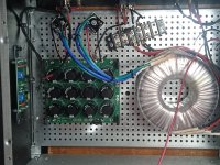
Now, the rectifiers. I idiot-proofed the rectifiers by marking with a Sharpie each corner with +, - or AC.
Then I attached them to the chassis diagonally to orient them to the board.
You can + and - horizontal and AC vertically ( I didn't plug in the secondary wires for clarity).
+ is toward the middle on both rectifiers.
Attachments

I don't believe you have any issues on the primary side of your transformer but I'll post the following as a potentially better explanation of how you're wired.
The one difference is the F5M PS has a single TH1 in series with the fuse instead of a TH for each primary winding.

The one difference is the F5M PS has a single TH1 in series with the fuse instead of a TH for each primary winding.
- Home
- Amplifiers
- Pass Labs
- Need Help with F5M Build