Says the regulated voltages should be 38VDC rather than 33VDC, so that should be checked out.
Maybe the pots need cleaning and adjustment.
Maybe the pots need cleaning and adjustment.
As I mentioned, I can adjust the pots to lower the regulated voltage, but I can't get it higher than a bit over 34 volts on either rail. VAC from the transformer is 26.7 for either half, about right for 56 VAC, center tapped.
I'm continuing to pound away at this project, determined to not let it get the best of me--you all know what that's like.
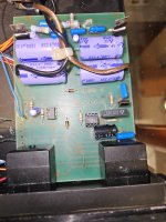
Not having a better plan, I replaced the six transistors regulating both rails. Feels like neurosurgery on those old, delicate boards. Powered it up, and positive rail can be adjusted to 33v, appropriate for the circuit according to the circuit diagram (attached). Negative rail I can't get to more than 27v, and the voltage-checking circuit continues to flash its LED. Both trimmers seemed within range when checked in-circuit, not acting twitchy or intermittent.
FWIW, the 220-ohm R11 heats up to over 100 °F quite quickly, but that seems only involved in the LED flasher circuit.
If anyone has suggestions, even of what to check, I'd love to hear them.
Attachments

I'm pretty sure that circuit's only function is to flash (A3) the LED for a few seconds until it times out (A2) and closes the mute relays.
It doesn't perform any voltage test.
It doesn't perform any voltage test.
Thanks, that's helpful.
Following on from that, what would cause the flasher to not stop? Does that mean I have both an issue with the flasher circuit and low voltage on one rail?
Following on from that, what would cause the flasher to not stop? Does that mean I have both an issue with the flasher circuit and low voltage on one rail?
Just a quick guess, it may be that a fault with the relay timing circuit could be loading the negative rail down, causing the excess heating of R11, the inability to set the negative regulator output to the desired level, and the LED to stay flashing.
This was triggered by seeing that the relay timing/LED flashing circuit is powered off the raw DC negative rail (seems a bit odd, but I'd guess it might be that the positive rail was higher-loaded in this circuit, so this may have helped balance the current draw between the two rails).
I'd suggest the following:
- Measure the raw DC voltages into the positive and negative regulators.
- Lift one end of R11 to isolate the relay timing circuit.
- Re-measure the raw DC voltages into the positive and negative regulators.
- See if you can adjust the negative regulator up to 33V now.
If so, then you need to troubleshoot the relay timing/LED flashing circuit. Some thoughts are:
- An issue with the 78L12 regulator. Maybe the replacement doesn't have the same pinout?
- Shorted relay coils? Never heard of this, but not impossible.
- That the LED still flashes suggests that the NE555Ps are both still ok, but that may be another thing to check.
Curious to see if this helps any.
Greg in Mississippi (who's 1st Audiophile-ish preamp was this unit's predecessor, the PS-III/LCC... and who later was part of a group mid-'80s of DIY'ers that scratch-built PS-IVs based on these schematics. I used it for many years until I tried my 1st tube-based phono preamp, a NYAL Super-IT, which was ok stock, but re-configuring the 1st stage cascode from 12AX7s to 6DJ8s to use the Joe Curcio Daniel input circuit made it a Super-Winner. BTW, that scratch-built group was painfully slow in those days before ubiquitous email... doing that via letters and packages was mongo slow!)

Very much appreciate the reply, Greg. That makes a world of sense and gives me several paths forward.
As for the regulator, I haven't been able to find a 78L12 in the exact same package as the one I swapped out because it had been running hot for a long period of time. In fact, I haven't been able to identify the (apparently obsolete) case: It's smaller than a T0220, slab-like with a chamfer on the top, with no hole or tab for a heat sink. Anybody know that one? If I can search with the proper case designation, find one and and maybe compare pinouts.
As for the regulator, I haven't been able to find a 78L12 in the exact same package as the one I swapped out because it had been running hot for a long period of time. In fact, I haven't been able to identify the (apparently obsolete) case: It's smaller than a T0220, slab-like with a chamfer on the top, with no hole or tab for a heat sink. Anybody know that one? If I can search with the proper case designation, find one and and maybe compare pinouts.
Pictures of the original 78L12?
Also of the replacement? & Do you have the datasheet for the replacement or at least a pinout of it?
& details of where which pins of the replacement went in relation to the schematic?
TY!
Greg in Mississippi
Also of the replacement? & Do you have the datasheet for the replacement or at least a pinout of it?
& details of where which pins of the replacement went in relation to the schematic?
TY!
Greg in Mississippi
Last edited:
Update... & apologies, I was looking at the relay timing circuit again and darn, I missed that it is powered from both the positive and negative rails. Sorry!
Lifting one lead of R11 will only cut the power from the negative rail. You'll need to lift one lead of R13 to cut the power from the positive rail.
With both out, that circuit is un-powered and you can then see if it is what is causing the negative regulator to not be adjustable to the required voltage.
Let us know what you find.
BTW, when you replaced the regulator transistors, were they exact replacements by P/N or equivalents?
Finally, IF you can live without the flashing LED, there are other simpler circuits you can substitute to cause a time-delay mute when the unit is powered on. SO if it is the relay timing circuit that is causing the issue AND we can't resolve it, we can provide some suggestions.
Greg in Mississippi
I've misplaced the original 78L12, but here's a picture of an NEC 78L05 for sale on eBay with the same case as the one I took out and replaced with a 7812 in a TO220 case. I can't find an older data sheet with this case. Current ones show T092 and a surface-mount version, so no idea about the pinout.
Attachments

Any updates?
I keep puzzling over the relay timing circuit to figure out exactly how it functions. While I am not yet clear what's going on, here's what I suspect so far...
- AFAIK, ALL NE555P pinouts in older 8-pin DIP packages that I've seen have pin 1 as ground, pin 8 as Vcc, and pin 3 as output (and I have schematics of circuits using this IC that predate the PS-IV that confirm those pinouts). AND the connections for these pins in the circuit seem to confirm that. AND this would infer that pin 8 would be between 4.5V to 16V (max 18V) aboe pin 1 when functioning.
- OTOH, ALL 78L12 3-pin package pinouts I've found have pin 1 as output, pin 2 as ground, and pin 3 as input. AND this infers that pin 2 as ground will always be at the lowest potential, with pin 3 as input highest, and pin 1 as output in-between (and very close to 12v above pin 2 ground).
- BUT the circuit has the 78L12 pin 2 (assumed ground and lowest potential) connected to the NE555P pin 8 (Vcc), which makes no sense when the 78L12 pin 1 (assumed output and highest potential) is connected to ground (also making no sense). AND 78L12 pin 3 (assumed input) connected to the raw DC negative rail via the 220R R11 when on also makes no sense (please confirm that is the ON connection, I infer that from the schematic, but it is not definitive).
- IF the 78L12 is being turned on to power the NE555P and relays at 12V in that circuit, that STRONGLY suggests the part you removed had a different pinout than the one you used as a replacement.
- OR perhaps the 78L12 is being used in a non-standard way, but I cannot make sense of that given its assumed pinout and how it is connected to the NE555P pin 8 Vcc and pin 1 ground AND the voltage levels relationship between the 3 78L12 pins.
IF after lifting one leg of R11 and R13 you can adjust the negative regulator to the desired -33V, that will indicate the relay timing circuit is causing that issue.
IF that happens, I suggest you next reconnect R11 & R13, but pull your replacement 78L12. IF the pinout of the replacement is different from that of the original (and if the NE555Ps have not been damaged by over-volting their absolute maximum of 18V), then you should still be able to see -33V out of the negative regulator. AND that may strongly suggest a different pinout of the original 78L12.
IF so, next thing is to measure the voltages where the 3 pins of the original 78L12 go, both with the on-off switch on and off, to give a better picture of what's going on.
Thoughts?
& hopefully I am not totally clueless about this or missed something key.
Greg in Mississippi
Thanks, Greg, no updates, but more thoughts and questions. I have to fit my electronics projects in between all of life's other obligations.
I cleaned up the barely readable PS schematic for posterity. The only thing I'm not sure about are the diodes 6–13, 1N4954 (zener?), as the handwriting was pretty bad and the numbers on those tiny glass diodes are next to impossible to read when installed. If you or anyone knows these to be correct or different, or any other changes needed, let me know and if needed I'll change and re-post.
I still don't know the pinout of the original 78L12 regulator, but if the drawing is correct in depicting the leads they come out of the case, then it shows the middle pin (3) as the input, pin 2 as the output and pin 1 as the ground. Am I correct in my reading of this? Can't tell from the diagram which side is the face, but for sure it doesn't match 7812 pinout.
If so, this is different from what the diagrams for the T0-220 show, reading left to right from face side: 1 input, 2 ground, 3 output. This means I have it installed incorrectly. Does that all sound right? Certainly would explain problem, as you say.
BTW, the transistors I replaced were the same part numbers as the originals
Attachments

Hello,
I am the source for the schematics that you guys are using, as I did warranty work on PS audio stuff many years ago, and I have the originals here. Diodes 6 - 13 are 1N4454, standard switching diodes, 1N4148 would probably work fine.
I also have the Rev B schematic, but it also shows the the strange pinout for the 78L12. My guess is that this is an error, as I have never heard of a 78L12 with that non-standard pinout.
If you have any other questions about the schematic let me know.
Take care,
Doug
Thanks for the info, Doug. Here's an updated drawing with the correct diode number. I'll trace the pin connections on the regulator and see if they are as shown on the drawing.
Do you know what that timing circuit is actually doing? If it's timing only, then that seems like a pretty complex way to accomplish that. If it's actually checking the rail voltages, then that makes more sense. But it can't be, since there's no connection shown to the main rails.
I have one rail that I can't get up to the correct 33v even after replacing all the transistors in the main PS circuit and checking the trimmers as best I can.
Attachments

Yes, definitely trace the connections on the regulator.
As far as I understand it is just a timing circuit, it definitely doesn't monitor the rails, so it's only purpose is to mute the outputs temporarily on power up.
One thing that I have found with PS Audio pcbs is the traces can be very delicate, so you may have a hairline crack in one of the traces causing problems. If you measure all of the voltages on each power supply transistor, they should be equal and opposite between the positive and the negative rail. If you post the voltages that are incorrect I may be able to narrow things down a bit for you.
Take care,
Doug
Buckapound,
Totes understand balancing different aspects of life.
On diodes D6-D13 in the regulator circuit, while I would swear that it reads 1N4954 as written, the evidence posted from Doug (The Peasant) PLUS that those diodes are not drawn as zener diodes (I have another Stan Warren hand-drawn schematic with actual zener diodes and he uses the correct symbol there), I believe they are 1N4454 general purpose diodes as Doug says. AND to cross-check, I have a regulator board here from PS (don't remember how I got it, that was 35 years+ ago! I first thought I had gotten it as a blank board and populated it, but the gold dot suggests to me it was populated and checked at PS). I just pulled one of the diodes roughly in the same positions (it has a set of 3 diodes and 2 diodes instead of 2 sets of 2 diodes as on the schematic you have). And the diode I pulled from one of the sets of 3 diodes IS a 1N4004 general purpose, not a zener. AND I can see the "00' on one of the diodes in one of the sets of 2 diodes, which I take as pretty strong evidence it is also a 1N4004. SO that also could be your negative regulator issue.
On the 78L12, I take the numbers on the schematic to correspond to the pins left to right when looking at the part face with the printing. AND how they are arrayed on the schematic doesn't necessesarily match the part pinout.
AND the 78L12 datasheets I looked at were for other packages (TO-92) and I assumed they had the same pinout as the TO-220, but I was wrong. SORRY. I have good representative TO-220 78L12 pinouts now and they are as you said, pin 1 input, pin 2 ground, and pin 3 output. Again sorry for the confusion.
Using that to reassess my statements, they now read:
- OTOH, ALL 78L12 TO-220 3-pin package pinouts I've found have pin 1 input, pin 2 ground, and pin 3 output. AND this infers that pin 2 as ground will always be at the lowest potential, with pin 1 as input highest, and pin 3 as output in-between (and very close to 12v above pin 2 ground).
- BUT the circuit has the 78L12 pin 2 (assumed ground and lowest potential) connected to the NE555P pin 8 (Vcc), which makes no sense when the 78L12 pin 1 (assumed input and highest potential) is connected to ground (also making no sense). AND 78L12 pin 3 (assumed output) connected to the raw DC negative rail via the 220R R11 when (assumed) on also makes no sense (please confirm that is the ON connection, I infer that from the schematic, but it is not definitive).
& as Doug says, the timing circuit is not monitoring the rails, just starting the NE555P timing circuits (with one likely causing the LED to blink for a set period of time and the other likely unmuting the outputs when that period of time is over).
Based on that now corrected info, I recommend the following steps...
- 1st, confirm whether the power switch connects the negative rail to R11 (220R) resistor when turned on... or when turned off. Again, I am assuming when on, but can't tell for sure based on the schematic.
- 2nd, trace the connections for the 78L12 in the relay timing circuit to confirm that the numbers on the schematic match pads for a pinout of 1-2-3 from left to right. & if they don't, let us know what they match.
- 3rd, confirm that the outputs are muted (shorted to ground) when the power is off. Again I assume that is true, that is how every mute circuit I am aware of works, but best to confirm.
Those things will help us better analyze what the circuit is actually doing.
Then...
- Lift one leg each of R11 and R13 to disconnect the relay timing circuit from power. See if you can adjust the negative regulator to the desired -33V.
- IF you still cannot adjust the negative regulator, then replace diodes D6-D13 with general purpose diodes (which is not a bad idea anyway, but hey, if it works ok with the zener diodes in, maybe leave well enough alone?), actual 1N4454 as indicated, 1N4148 as Doug suggested, or 1N4004 as in the PS Audio regulator board I have here. Any of these types should do ok. AND then see if you can adjust the regulators ok.
- Once you have the regulators set to +-33V, reconnect R11 & R13, but pull your replacement 78L12. Then power the unit up and measure the voltages where the 3 pins of the original 78L12 go relative to ground, both with the on-off switch on and off.
With that info, I suspect we can suggest how to connect the TO-220 78L12 to make things work ok again.
Dang, sorry this has been such a slog!
Greg in Mississippi
Attachments


Last edited:

Thank, Greg, I'll digest that and see what I can do.
I can confirm that the way the 78L12 is shown in the schematic is in fact the way it is connected: pin 1 to ground, pin 2 to leg 8 (top right in the schematic) of the timer chips and pin 3 to the near side of R11, via the power switch.
So, this means the pinout of that vintage 78L12 is utterly different from the standard pinout of today's 7812s. Knowing this is something that needs fixing, I will definitely re-wire that, although getting those three-pin components off the board without clipping the leads is a bear.
Doug, having re-capped the whole thing, I know what you're taking about as far as that board: thin copper, narrow traces and tiny pads, too. just a nightmare to work on. I only lifted a couple of pads and lost one. I've tried to be super careful, clipping leads, pulling them through from the front, then drilling out the remaining solder from the back side to avoid putting too much heat or stress on the tiny pads. Feels like neurosurgery.
Takes me more than an hour and a half to remove the board and put it back. I did install a terminal block for power and a small one for the LED so I can take the whole board out of the chassis. I have way too much time in this; I'm really driven by stubbornness at this point.
But It's hard to imagine that having the timer circuit incorrect would affect one rail, but we'll see. Maybe it's pulling too much current.
Really appreciate both your insights!
— Randy
@guy48065, interesting, I had not seen that version of the PS-IV in the flesh before, but I have a PS-IV owners manual downloaded from HiFi Engine that shows a schematic with that version of the regulator board using 2 regulator chips instead of a discrete regulator as in later versions. I can post that page if interested, they aren't accepting new accounts currently and if you had one with no activity in the last 3 years (like mine), it has been deleted. Otherwise I'd just point you there.
I think I have something like 8 different PS Audio regulation scheme schematics from that era. They were experimenting a LOT back then!
Randy, an interesting coincidence, there's a PS-IV similar to yours on EBay right now for FAR TOO MUCH $$$$$. It has some differences, like the volume and balance controls mounted on a circuit board instead of point-to-point wired and a different AC-DC rectifier setup on the power supply / relay timer circuit board, among other things. BUT the interesting thing is that it CLEARLY shows significant heat damage to the circuit board where that 78L12 regulator chip is mounted, MUCH more than yours.
You can find it here:
https://www.ebay.com/itm/1766983038...SNq8YkQR3u&var=&widget_ver=artemis&media=COPY
Giving us the voltages at the 78L12 with the circuit both on and off, which way it is on, switch open or closed, and whether the relays mute when powered or not, will help a LOT in determining how next to try a replacement 78L12.
AND
BTW, while I am suspecting the negative regulator output is related to the 78L12 replacement, it still could be caused by using the zener diodes we thought were specified instead of GP diodes. I'd suggest you plan to replace them anyway after the removved-78L12 test & go with 1N4454 if you can get them easily, with 1N4148 as Doug suggested if not.
On un-soldering, are you using solder wick? It works well for me by allowing me to remove all the solder from the joints (especially well in these old non-multiple layers / no-through-hole plated pads) where I can use a small-tipped needle-nose plier to straighten the leads and pull the part out with no pad stress.
& just a curiosity question... where the heck are the muting relays? Am I just blind or are then hidden in the top views?
Such fun!
Greg in Mississippi
P.S. There's another PS-IV listed without an AC power supply at $139 and taking offers... maybe consider asking the seller for pix & if it is the same vintage, make him an offer for one up for spares? It is here:
https://www.ebay.com/itm/3961000197...SNq8YkQR3u&var=&widget_ver=artemis&media=COPY
Wow, the way they kept changing parts reminds me of this old British sports cars (had a TR-250 at one point), where there was barely anything that was standard across a model, especially the Lucas electrical stuff. Crazy that the 78L12 chip was so overloaded. Clearly a design flaw.
Muting relay (just one) on my unit is way at the other end of the input board. It's the blue encapsulated oblong thing in the eBay pic.
I've got a few 7812 chips on order. Annoying that in the entire metro area of Chicago, there's no place you can just pop into to buy common stuff like that. So, will report back in a few days.
On the diodes/zeners: I did not replace any of those, so that's unlikely to be a problem.
I have and do use solder wick and it's good for some things, but I find for parts removal it's hard to get all the solder off without applying to much heat and frying the glue that holds the foil to the board. So, prefer prefer to clip, pull and drill a hole just barely big enough to fit the new component leg through. Very little stress on that delicate board.
Yes, fun, but, the last thing I need is another one of these.
--Randy
- Home
- Source & Line
- Analog Line Level
- Need PS Audio PS IV schematic