FWIW, I've found the method in the first post works well. At least well enough for me. Way back when I bought a couple full tubes of IRFP240s and IRFP9240s for an A75 build.
Using a generic 12V cigarette lighter type supply (14V actual output) and 100R in series to get roughly 100 mA with the devices in free air. I measured Vgs after 1 minute. The lot was mostly matched within 9 mV. I checked several devices in service and the Source resistor voltages were within a few mV.
Last week I measured the same lot leftovers again for an F5T build at roughly 650 mA. For this I clamped the DUT to a heat sink. Again every device was within 5 mA. I retested each chosen set (0-1 mV match) back to back to try to account for the heat sink having warmed up with no change in Vgs. The Vgs differences between devices matched the Vgs differences at 100 mA, within my meter's resolution.
I don't quite feel comfortable not matching when pulling devices from the same lot, but it sure makes matching easier.
Last edited:
FWIW, I've found the method in the first post works well. At least well enough for me. Way back when I bought a couple full tubes of IRFP240s and IRFP9240s for an A75 build.
Using a generic 12V cigarette lighter type supply (14V actual output) and 100R in series to get roughly 100 mA with the devices in free air. I measured Vgs after 1 minute. The lot was mostly matched within 9 mV. I checked several devices in service and the Source resistor voltages were within a few mV.
Last week I measured the same lot leftovers again for an F5T build at roughly 650 mA. For this I clamped the DUT to a heat sink. Again every device was within 5 mA. I retested each chosen set (0-1 mV match) back to back to try to account for the heat sink having warmed up with no change in Vgs. The Vgs differences between devices matched the Vgs differences at 100 mA, within my meter's resolution.
I don't quite feel comfortable not matching when pulling devices from the same lot, but it sure makes matching easier.
Do you feel 100mA is a better representation of the true Vgs at real operational conditions than 5mA? Did you get to test at 5mA to see if it made a difference? I suppose it will heat up quite Abby at 100mA and Vgs will probably be lower?
I haven't tested output devices at 5 mA. I went with 100 mA and then 650 mA because that is the expected operating condition - the way Mr. Pass suggested matching in the A75 article. I matched that amp's front end devices at 5 mA and the VAS devices at 20 mA.
That said, there wasn't much match difference between 100 and 650 mA. Further down on the curve there might be. Take a look at the Vgs vs. current curves. You may want to measure at a current more representative of your standing bias.
Yes, Vgs dropped a bit as the devices heated up, but seemed to stabilize at about a minute whether free air or clamped to a heat sink. I used a side of the store 5U enclosure for the sink.
Last edited:
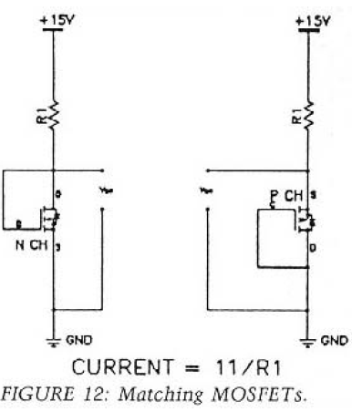
I imagine diyAudio members would prefer a constant current source which sources current: from a positive power supply, into a grounded load. Then when measuring Nchannel MOSFETs, the device under test is connected: (source = GND), (gate = drain = CCS output), and the Vgs meter is connected between gate and GND.Does the VCCS opamp require the opamp to be rail to rail input when powered from the same Zero Volts as the CCS?
Can an ordinary BJT input with pnp for the LTP perform when the Vee is at the same Zero Volts as the CCS.
Is there any advantage or disadvantage in using a FET input opamp?
In this scenario you want to build your current source using an opamp whose common mode input voltage includes the top supply rail. It is not required to be RRIO because neither the input nor the output will go anywhere near the bottom supply rail.
You want opamp input bias current to be less than 0.1% of the minimum possible output current; if I_out_min is 1mA then you want input bias current to be less than 1uA. Fortunately 99.9% of opamps meet this requirement.
Me, I would use my standard workhorse CMOS opamp: the MCP6022. Its precision is acceptable (1 pA input bias current, 0.5mV input offset voltage, 90 dB DC gain), its speed is adequate (10 MHz GBW, 7V/us slew), its price is acceptable ($1.31 qty=1), and it happens to be RRIO too. Plus, being CMOS, its input pins do not include back-to-back protection diodes. Thus it does nothing weird when the input pins are 2.5 volts apart, unlike the 5532 and many many other opamps. Rookie CCS designers often get an ugly surprise when the load is disconnected and suddenly the opamp's input pins become 2.5 volts apart.
Since the MCP6022 max supply voltage is 5.5V I'd include a zener diode + resistor "regulator" followed by the standard opamp power pin bypassing.
With a 5V opamp you want the CCS output transistor to have a relatively low threshold voltage; then Vgs=4V will give many amperes of drain current, which is more than enough. Fortunately $1.27 will buy the Infineon SPP15P10PL whose threshold voltage is 2V max. Datasheet figures, copied below, show that it can easily achieve the target 2.5 amperes of drain current, with a Vgs comfortably below the 5V power supply.
_
Attachments


Member
Joined 2009
Paid Member
I haven't tested output devices at 5 mA. I went with 100 mA and then 650 mA because that is the expected operating condition - the way Mr. Pass suggested matching in the A75 article.
Yup - and that's why you see a heatsink in the image I posted
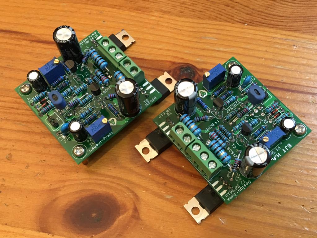
I'm finding that I am using this rig a lot now that I have it. Maybe t doesn't matter for P vs N channels but since I have it, I am even trying to match Vgs on N channel and P channels on the MOSFETs of my Juma head amp.
Pass FET tester
I recently build this tester togehter with a friend og mine. We are both building an Aleph 5 and thought having a permanent tester would be handy. So here is the schematic:

And the box looks like this:

I use a PC power supply at 19VDC, which gives slightly lower test currents. The A and V modules are cheap AliExpress types.
I recently build this tester togehter with a friend og mine. We are both building an Aleph 5 and thought having a permanent tester would be handy. So here is the schematic:
And the box looks like this:
I use a PC power supply at 19VDC, which gives slightly lower test currents. The A and V modules are cheap AliExpress types.

That's a very handy tool to have! Are those just regular 1/4DIN mV resolution LED display panels?
That's a very handy tool to have! Are those just regular 1/4DIN mV resolution LED display panels?
Hi!
The modules I used are these: ammeter and voltmeter
There is no floating measurement possible with the voltmeter (3-wire).
In the schematic you will notice that the voltage drop across the ammeter is included in the voltmeter readings.
But for matching purposes this doesn't really matter.
If one of the "layout masters" on this forum could so kindly please make a PCB for all of us to have a handy dandy tester, that would be great. 😀
@m0rten, Thanks for the links! That's an amazing price for a 5-digit LED panel meter! $4.67 shipping included, yikes. I am going to have to buy a dozen or so 🙂

@m0rten, Thanks for the links! That's an amazing price for a 5-digit LED panel meter! $4.67 shipping included, yikes. I am going to have to buy a dozen or so 🙂
If one of the "layout masters" on this forum could so kindly please make a PCB for all of us to have a handy dandy tester, that would be great. 😀
@m0rten, Thanks for the links! That's an amazing price for a 5-digit LED panel meter! $4.67 shipping included, yikes. I am going to have to buy a dozen or so 🙂
There really is little need for a PCB for my unit. It is made of 2 pcs of Veroboard, one at the top with only the ZIF and the jumpers.
The second is piggy backed below and contains the 4 resistors. The rest is cabling.
PS. Make sure the voltmeter you order has 3 lines, not 2.
What happened to Easy Peasy? The first post looked do-able and then all hell broke loose and nobody ever presented an easy-peasy tester for MOSFETs.
The tester is in Post 1, seems to work for me. Lots of folks had suggestions to make it better with more complexity. But as a means to do some initial sorting and matching, it works well enough.
Certainly much much better than randomly pulling MOSFETs from a tube and hoping for the best. 🙂
If it’s good enough for Nelson Pass to use and write an article about it, it can’t be too bad.
Certainly much much better than randomly pulling MOSFETs from a tube and hoping for the best. 🙂
If it’s good enough for Nelson Pass to use and write an article about it, it can’t be too bad.
Last edited:
Pretty sure Nelson Pass was trying to show the least-terrible circuit that hobbyists could easily assemble themselves, using the fewest possible pieces of test equipment, which still gives beneficial (better than coin-flipping) results.

Need of matching
Hi,
I am still quite new to the MOSFET topic and therefore have a question. With an amplifier that has only one N- and P-MOSFET for each channel, do I need matched devices? I.e. do I have to match the N-MOSFET with the P-MOSFET of one channel and maybe between left and right channel?
I skimmed the article from Nelson Pass and understood that I only need to match the MOSFETs if I have several N or P on one channel.
Not in the usual topologies NP has used, the primary reason to match in his designs is when there are multiple mosfets that will be operated in parallel in order to increase amplification power. There is variation in the amount of voltage that each mosfet requires to turn on (Vgs) and tight matching ensures that your mosfets are appropriately sharing current and operating in unison. If poorly matched, you can have a situation where some are on while others are not.
I have read that there can be some very minor benefits from matching N to P, but these statements have always been accompanied by an acknowledgement that this is of very little benefit and concern. As I understand it, in most cases there are many other issues usually left unaddressed that would have larger impacts on performance than N to P Vgs matching.
Caveat to all of this is that I am not an amplification expert, so everything I know is really just as it applies to Nelson's circuits, in particular the F4. I don't understand much about underlying principles unfortunately.
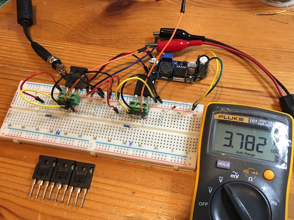
I think I might have taken the easy out of "Easy Peasy" and instead created the Franken-Tester. I started with this thread, so I figure I might as well post here. I began with a simple circuit as proposed here, then graduated to the circuit using a CCS, then to four channels with CCS with switch box to meter. I'm building this to prepare for measuring complimentary pairs of IRF 520/9520 both accurately and quickly. I really never thought to ask for advice (with the exception of the CCS) while building...I just kinda did what made sense to me. I'd love to know how others test multiple FET's.
Attachments
-
 AC98E6F0-4DA7-48F5-B928-3B6ED0810A8D_1_201_a.jpeg519.1 KB · Views: 211
 -
 ADF5FCAA-BA86-4AB5-8D6F-28FA662F4E48_1_201_a.jpeg457.3 KB · Views: 225
 -
 26AAA05A-6750-4043-9FDB-635F13D157DF.jpeg514.9 KB · Views: 227
 -
 068255C8-F842-4914-84ED-0E77044EA50F.jpeg367.8 KB · Views: 231
 -
 AA4D3769-35F9-4F8D-A0E9-9C01877761FF.jpeg492.5 KB · Views: 211
Last edited:
Hi Kevin,
Nice setup! Woofertester will be testing 1200 IRFP240’s for me to get matched triplets for the cascode portion of the SuSyLu. He’s got a commercial grade Keithly instrument tester with a custom script to automate as much as possible.
Nice setup! Woofertester will be testing 1200 IRFP240’s for me to get matched triplets for the cascode portion of the SuSyLu. He’s got a commercial grade Keithly instrument tester with a custom script to automate as much as possible.
- Home
- Amplifiers
- Solid State
- Nelson Pass' Easy Peasy MOSFET Vgs Measurement